Adafruit PiCowbell CAN Bus for Pico - MCP2515 CAN Controller
We have ✅ 4 available of the AF-5728 in our Sydney warehouse. An extra 100 units available with a short lead time.
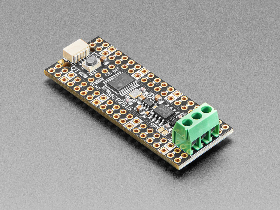
The Adafruit PiCowbell CAN Bus adds CAN bus connectivity to your Raspberry Pi Pico or Pico W, making it easy to interface with automotive, robotics, and industrial sensor networks. Built around the popular MCP2515 CAN controller and TJA1051/3 transceiver, it communicates over SPI and supports both standard and extended frame formats at up to 1 Mbps.
CAN bus is a two-wire differential protocol originally designed for vehicles but now widely used in robotics and sensor networks. It offers better range and noise immunity than I2C, with simple two-wire connections that allow new nodes to join anywhere on the shared bus. Built-in collision detection ensures reliable communication even with multiple devices transmitting simultaneously.
Key Features
- MCP2515 CAN Controller – Well-supported chipset with drivers for Arduino and CircuitPython, requires only SPI plus two GPIO pins (CS and IRQ)
- TJA1051/3 Transceiver – Handles the physical CAN bus signalling with robust noise immunity
- 5V Charge-Pump Generator – Produces clean 5V for the transceiver from the Pico's 3.3V supply, no external power needed
- 3.5mm Terminal Block – Pre-soldered for quick access to CAN High, CAN Low, and ground lines
- 120Ω Termination Resistor – On-board with a cuttable jumper to disable when not at the end of a bus
- Pre-Connected CS and INT Pins – Default GPIO #20 (CS) and #21 (INT), re-assignable via solder jumpers on the underside
- STEMMA QT / Qwiic Connector – Right-angle JST SH connector for I2C devices on GPIO 4 (SDA) and GPIO 5 (SCL)
- Reset Button – Conveniently placed for quick program restarts
- Gold-Plated Pads – Every pad has a duplicate hole for easy solder-jumpering; ground pads marked with white silkscreen
Header Options
The PiCowbell ships with an assembled PCB and header that requires soldering. Several configurations are available depending on your setup:
- Stacking Headers – Plug into a breadboard or other accessories with sockets
- Socket Headers – Plug the Pico directly in for a solid, compact connection
- Short Socket Headers – Ultra-slim pluggable design; pair with Short Plug Headers on the Pico for a skinny sandwich
- Direct Soldering – Most compact and inexpensive, but permanent
Pin Configuration
- SPI (Arduino Philhower core) – Default SPI on GPIO 16 (MISO), 18 (SCK), and 19 (MOSI)
- SPI (CircuitPython / MicroPython) – Configure SCK=18, MOSI=19, MISO=16 in code
- I2C – GPIO 4 (SDA) and GPIO 5 (SCL), pre-configured in Arduino Philhower core; set manually in CircuitPython/MicroPython
- CAN CS – GPIO 20 (re-assignable via solder jumper)
- CAN INT – GPIO 21 (re-assignable via solder jumper)
Ideal For
- Reading OBD-II vehicle diagnostics via CAN bus
- Robotics sensor and actuator networks
- Industrial automation and monitoring
- Custom CAN bus projects with Raspberry Pi Pico or Pico W
Package Contents
- 1× Adafruit PiCowbell CAN Bus PCB (assembled with terminal block)
- 1× Header (requires soldering)
Resources
The Adafruit PiCowbell CAN Bus for Pico - MCP2515 CAN Controller appears in the following collections: