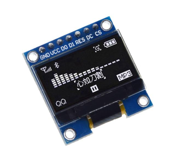
0.96" 7pin 128X64 OLED Display Module White
We have ✅ 52 available of the LB-LR0085 in our Sydney warehouse.
The OLED display operates within a wide voltage range (3.3V-5V DC), and can handle extreme conditions with a working temperature range of -30°C to 80°C. Its small form factor (27mm x 27mm x 4.1mm) makes it a perfect fit for compact designs.
The SSD1306 driver IC ensures reliable communication using an I2C interface, requiring only two I/O ports. Whether you’re developing a battery-powered project or experimenting with various microcontroller platforms, this OLED display provides exceptional performance with minimal power draw.
Key Features:
- Display Size: 0.96"
- Resolution: 128x64
- Colour: Blue
- Viewing Angle: >160°
- Voltage: 3.3V-5V DC
- Power Consumption: 0.04W (during normal operation)
- Working Temperature: -30°C to 80°C
- Dimensions: 27mm x 27mm x 4.1mm
- Driver IC: SSD1306
- Communication: I2C (2 I/O ports)
Hookup Guide for 0.96" 7-pin 128x64 OLED Display Module (I2C)
- 0.96" 128x64 OLED Display Module (7-pin, I2C)
- Arduino (Uno, Nano, or any 5V/3.3V-compatible board)
- Jumper wires
- Breadboard (optional)
- 4.7kΩ resistors (for I2C pull-up resistors, optional but recommended)
- GND - Ground (Connect to the ground of your microcontroller)
- VCC - Power supply (3.3V or 5V, depending on your microcontroller)
- D0 (SCL) - I2C Clock Line (SCL)
- D1 (SDA) - I2C Data Line (SDA)
- RES - Reset pin
- DC - Data/Command control pin
- CS - Chip Select (for SPI, not needed for I2C)
VCC | 5V (or 3.3V) | Power
D0 (SCL) | A5 (Uno/Nano) | I2C Clock (SCL)
D1 (SDA) | A4 (Uno/Nano) | I2C Data (SDA)
RES | D4 | Reset (connect to digital pin)
DC | - | Not used in I2C mode
CS | - | Not used in I2C mode
- Open the Arduino IDE and go to Sketch > Include Library > Manage Libraries.
- In the Library Manager, search for "Adafruit SSD1306" and click "Install."
- Search for "Adafruit GFX" and install that as well.
cpp
Copy code#include <Wire.h>
#include <Adafruit_GFX.h>
#include <Adafruit_SSD1306.h>

// OLED display width and height, in pixels
#define SCREEN_WIDTH 128
#define SCREEN_HEIGHT 64

// Reset pin for the display
#define OLED_RESET 4
Adafruit_SSD1306 display(SCREEN_WIDTH, SCREEN_HEIGHT, &Wire, OLED_RESET);

void setup() {
  // Initialize serial communication for debugging
  Serial.begin(9600);

  // Initialize the OLED display
  if (!display.begin(SSD1306_I2C_ADDRESS, OLED_RESET)) {
    Serial.println(F("SSD1306 allocation failed"));
    for (;;); // Don't proceed, loop forever
  }

  // Clear the buffer
  display.clearDisplay();

  // Display text
  display.setTextSize(1);
  display.setTextColor(SSD1306_WHITE);
  display.setCursor(0,0);
  display.println("Hello, OLED!");
  display.display();
}

void loop() {
  // You can add more code here for dynamic content
}
- Connect your Arduino to your computer via USB.
- Copy and paste the example code into the Arduino IDE.
- Select the correct board and port under Tools > Board and Tools > Port.
- Click Upload.
- No display: Double-check wiring, especially the power and I2C connections (SCL and SDA).
- Flickering or random behavior: Ensure proper pull-up resistors on the I2C lines if your microcontroller doesn’t have internal ones. Use 4.7kΩ resistors from the SCL and SDA lines to VCC.
- OLED not initializing: Verify that the correct reset pin is defined in the code (OLED_RESET pin).
The 0.96" 7pin 128X64 OLED Display Module White appears in the following collections:


