Electronics at Scouts
🔧 Scouts Electronics Adventures
This week at Scouts, we’ll be diving into the exciting world of electronics! From soldering a LAMP kit to coding with a Raspberry Pi Pico to make a Trip Wire, you’ll get hands-on with real tools and components. These activities are designed to be fun, creative, and safe — while giving you a taste of what real engineers do.
1. Soldering Station (Lamp Kit)
What you’ll do:
You’ll learn the basics of soldering while building a simple lamp PCB kit. Some resistors are pre-soldered to save time, so you can focus on mastering the technique of making good solder joints.
Key tips for Scouts:
-
Hold the soldering iron like a pen.
-
Heat the joint, not the solder.
-
Feed solder onto the hot pad/lead, not the iron tip.
-
NEVER touch the hot tip.
-
Pay attention to polarity: LEDs have a + and – (long leg = positive).
- Always place the iron back in its stand.
Takeaway: You’ll make something permanent you can be proud of — your very first step into real electronics!
2. Laser Module
About the module:
A red laser module produces a focused beam of light (around 650 nm). Inside the small cylinder is a diode, a driver circuit, and a lens. These are the same modules used in laser pointers, alignment tools, and fun DIY projects.
What you’ll do:
-
Make an AA battery pack to power the module.
-
Learn to strip and crimp wires so your header fits properly.
-
Test your pack with an LED before using it on the laser.
Key safety rules:
-
Never look directly into the beam — even low-power lasers can damage eyes.
-
Don’t point at mirrors or shiny surfaces (reflections can be just as dangerous).
-
Never aim at people, animals, or aircraft.
-
Try running your “trip wire” beam around a corner for extra fun.
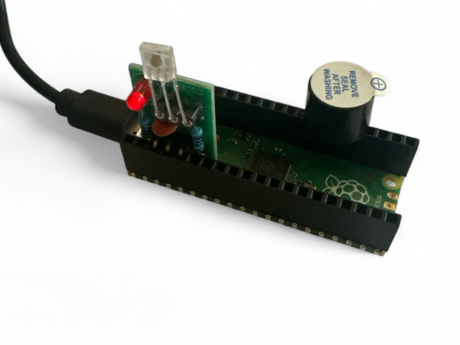
3. Pico Trip Wire Project (Coding + Sensors)
Now we’ll combine coding with hardware using the Raspberry Pi Pico.
What you’ll do:
-
Insert the laser detection module into GP2.
-
Add a buzzer to GP19.
-
Explore the MicroPython code that turns the Pico into a trip-wire alarm.
-
See how the code “watches” the laser beam, ignores glitches, and sounds the buzzer if the beam is broken.
- Edit the code - Install Thonny on your laptop and test changing the code.
- Design an enclosure in Tinkercad so sunlight doesnt trigger the module.
Key notes for Scouts:
-
Breadboards have rows (connected across) and rails (+ and –).
-
Match red rails to 3.3V and blue/black rails to GND.
-
Resistors can face either way, but LEDs must go the right way (long leg = +).
-
We are using 1s and 0s: HIGH/LOW signals.
-
The code uses if statements: if laser seen → LED ON, buzzer OFF.
Takeaway: You’ll see how hardware and software work together to build a real security system.
4. DIY Switches & Triggers (Exploring Digital Inputs)
Electronics isn’t just about lasers — everyday switches and sensors are just as powerful.
What you’ll do:
-
Use the Pico to experiment with digital inputs on GP2 and outputs on GP19.
-
Try different triggers:
-
Reed switch (magnet-controlled)
-
(Optional) PIR motion sensor
-
Use these to turn LEDs and buzzers on and off.
Key notes for Scouts:
-
Switches are just doors for electricity: closed = ON, open = OFF.
-
With a pull-up resistor, the Pico keeps an input HIGH until a switch pulls it LOW.
-
Tilt and reed switches make it playful — shake, tilt, or use a magnet to trigger your circuit.
Takeaway: You’ll learn how real-world actions — pressing a button, tilting a sensor, or waving a magnet — become digital signals the Pico can understand.
🌟 General Tips for Scouts
-
Safety first: hot irons, sharp wire ends, and even low-voltage electricity need care.
-
Check polarity: LEDs, buzzers, and sensors usually have + and –.
-
Don’t panic: if it doesn’t work, it’s usually just a small wiring error.
-
Experiment! Try swapping one sensor for another while keeping the same code — you’ll see how all digital inputs are just “yes/no” signals to the Pico.
$ python3 main.py


# ------------------------------------------------------------
# Laser “seen/not seen” detector with simple software filtering
# Target: MicroPython (e.g., Raspberry Pi Pico)
#
# What it does:
# - Watches a digital input from a laser receiver module.
# - Uses a tiny "debounce-like" filter so brief glitches are ignored.
# - Turns the onboard LED on when the laser is detected.
# - Drives a buzzer when the laser is NOT detected.
#
# Key ideas you'll see below:
# - Digital input with (optional) internal pull-up.
# - Polling in a loop at a fixed interval (every few milliseconds).
# - Measuring time between changes to ensure a stable state.
# ------------------------------------------------------------

from machine import Pin
import utime

# -----------------------------
# Pin numbers (GPIO identifiers)
# -----------------------------
# Change these to match your wiring. Numbers are GP pin numbers, not physical pin numbers.

RX_DO_PIN   = 2   # Receiver's DO output connected to GPIO 2 (GP2)
LED_PIN     = 25  # Onboard LED on the Pico is GPIO 25 (GP25)
BUZZER_PIN  = 19  # Active buzzer control pin wired to GPIO 19 (GP19)
                 # Make sure your wiring and comment match!

# Some receiver boards want a specific pin held HIGH (e.g., to power or enable something).
# Here GP3 is set as an output and driven HIGH at ~3.3 V. This is so the laser module has power
gp3 = Pin(3, Pin.OUT)
gp3.value(1)  # Keep GP3 at a steady logic HIGH

# -----------------------------
# Tuning / configuration knobs
# -----------------------------

STABLE_MS = 40  # How long (in milliseconds) a new reading must remain unchanged
                # before we accept it as the "real" state. Helps ignore brief noise.
POLL_MS   = 2   # How often (in milliseconds) we sample the input in the main loop.

# Lots of receiver modules have an "open collector" type output and expect a pull-up.
# If set to True, we enable the Pico's internal pull-up resistor on the input pin.
# That means: idle = HIGH, and the module pulls it to LOW when the laser is seen.
USE_INPUT_PULLUP = True

# -----------------------------
# Input setup and helper function
# -----------------------------

if USE_INPUT_PULLUP:
    # Configure RX pin as input with an internal pull-up to 3.3 V.
    rx = Pin(RX_DO_PIN, Pin.IN, Pin.PULL_UP)

    # With pull-up: LOW means "detected" (the module actively pulls the line down).
    def laser_seen():
        # rx.value() returns 0 for LOW, 1 for HIGH
        return rx.value() == 0
else:
    # No pull-up: depends on your module. Often HIGH will mean "detected".
    rx = Pin(RX_DO_PIN, Pin.IN)

    def laser_seen():
        return rx.value() == 1

# -----------------------------
# Output devices: LED + buzzer
# -----------------------------
# value=0 sets their initial state to OFF.

led    = Pin(LED_PIN, Pin.OUT, value=0)      # Onboard LED off initially
buzzer = Pin(BUZZER_PIN, Pin.OUT, value=0)   # Buzzer off initially

# -----------------------------
# State variables for filtering
# -----------------------------

stable_state = False       # The last "accepted" (filtered) state: True=laser, False=no laser
last_sample  = False       # The most recent raw sample read from the pin
last_change  = utime.ticks_ms()  # When the raw sample last flipped (timestamp in ms)

# ---------------------------------------
# Main loop: poll, filter, and take action
# ---------------------------------------
while True:
    # 1) Read the raw input (True if laser is seen, per laser_seen() definition above)
    sample = laser_seen()

    # 2) If the raw reading changed since last time, remember *when* it changed.
    #    We don't immediately trust the new value; we wait to see if it "sticks".
    if sample != last_sample:
        last_sample = sample
        last_change = utime.ticks_ms()  # mark the time of this change

    # 3) Has the raw reading stayed the same for long enough (STABLE_MS)?
    #    If yes, and it's different from our current accepted state, we accept it now.
    if utime.ticks_diff(utime.ticks_ms(), last_change) >= STABLE_MS and sample != stable_state:
        stable_state = sample  # accept the new stable state

        # 4) Take action based on the accepted (filtered) state
        if stable_state:
            # Laser detected
            print("Laser detected")
            led.value(1)   # LED ON
            buzzer.value(0)  # Buzzer OFF
        else:
            # Laser not detected
            print("No laser")
            led.value(0)   # LED OFF
            buzzer.value(1)  # Buzzer ON

    # 5) Wait a tiny bit before sampling again.
    #    Smaller POLL_MS = faster response but more CPU usage.
    utime.sleep_ms(POLL_MS)
