Little Bird
Monkey Board
Overview Designed in Australia, the DAB+ FM Digital Radio Development Board Pro provides a platform for developing and evaluating DAB+, SlideShow and...
Get notified when back in stock
Overview
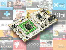
Designed in Australia, the DAB+ FM Digital Radio Development Board Pro provides a platform for developing and evaluating DAB+, SlideShow and FM receiver. The board contains a Keystone T2_L4A_8650C DAB/FM module and a Microchip PIC18F14K50 microcontroller. The T2_L4A_8650C module is an ultra low power DAB/FM receiver module with the following features:
- ETSI EN 300 401 compliant receiver
- DAB/DAB+ sensitivity to -99dBm (typical)
- Decodes multiple audio services up to 256kbps without external RAM
- FM with RDS (*** RDS reception only available for station name, station text and genre and is subjected to certain condition of power level and frequency deviation)
- Combined antenna input for FM / Band3
- Support DAB L-Band reception (*** Although the Keystone module supports L-Band, the SMA connector has no connection to the L-Band pin, customer will need to solder a separate antenna and other passive components to make it work.)
- Serial control interface
- RoHS compliant
- SlideShow
- EPG (hardware support, software under development)
The Microchip PIC18F14K50 provides a USB to Serial interface for the T2_L4A_8650C module to communicate with the host PC. Despite the sample code provided in this Development Board for communicating with the board is based on serial communication, user can analyse the serial communication and implements a driverless HID protocol by rewriting the firmware on the PIC18F14K50.
New SlideShow Feature
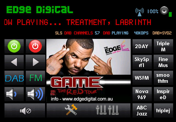
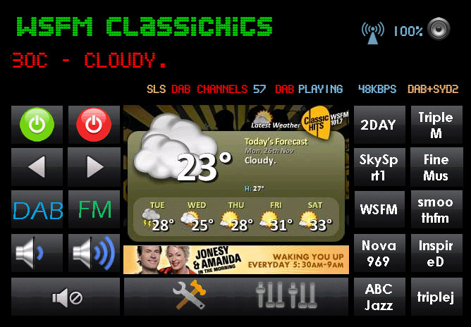
With an upgrade module using the KeyStone T2_L4A_8650C, this board now support SlideShow. Slideshow adds visual content (slides) to radio broadcasts on DAB or DAB+. It enhanced the digital radio with visuals using images in JPEG or PNG format.
Board Dimension
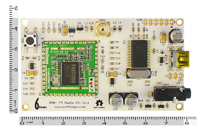
78mm x 45mm
What can you do with it?
- Build a PC controlled DAB+ FM Digital Radio with SlideShow
- Build a CAR PC DAB+ FM Digital Radio with SlideShow
- Build a standalone DAB+ FM Digital Radio (requires external microcontroller)
Feature Summary
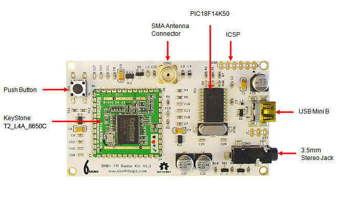
- KeyStone T2_L4A_8650C DAB/DAB+/FM radio module
- Microchip PIC18F14K50 USB Flash Microcontroller
- 12 Mhz crystal
- standard ICSP programming port for programming the PIC18F14K50
- EXT port logic signal for controlling external audio chip power and mute
- status LED, RX (orange) and TX (green)
- power LED (red)
- Bootloader push button
- 1.2VDC, 1.8VDC, 3.3VDC LDO
- 3.5mm stereo jack
- SMA antenna connector
- Dimensions : 78mm x 45mm
HARDWARE DESCRIPTIONS
Power Supply Circuit
The board is typically powered by 5VDC from USB. The PIC18F14K50 is drawing power directly from the USB. From the USB’s 5VDC, the power is further distributed into 1.2VDC, 1.8VDC and 3.3VDC LDO to the KeyStone T2_L4A_865C module. The power of these three LDO is controlled by the SHDN pin.
Microchip PIC18F14K50
This microcontroller is used to provide a Virtual Serial Port to the KeyStone module. It is flashed with a customised CDC RS-232 Emulation Demo firmware. Other than performing the standard serial emulation, it also control the power, reset and audio shunt of the KeyStone module.
Reset Circuit
Reset of the module is performed by RESET pin emulated by DTR of the virtual serial port.
ICSP
The ICSP programming port is the standard Microchip’s In-Circuit Serial Programming port and is compatible with Microchip’s PICkit.
EXT
EXT port has two 5V logic signals, ˉSHDN and ˉSHNT. They are used to control external audio circuitry’s power and mute.
Push Button (SW1)
This button, when pressed during a power-up, will trigger the PIC18F14K50’s USB HID bootloader in programming mode.
Packing List
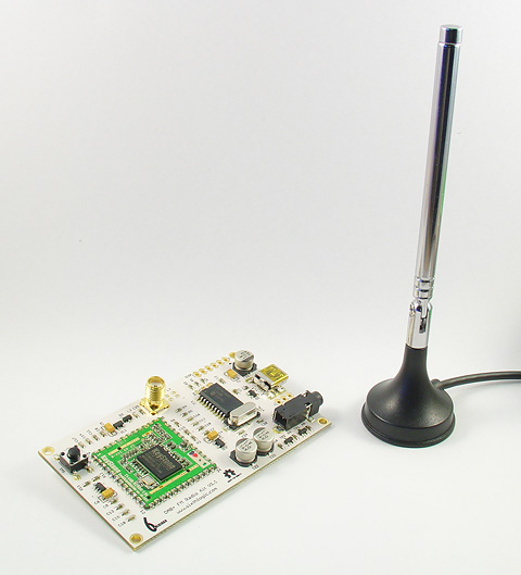
- 1 unit of DAB+ FM Digital Radio Development Board Pro with KeyStone T2_L4A_8650C
- 1 unit of retractable antenna
Pre-installed Software
- Microchip's USB bootloader (programming the board using a normal USB cable)
- Microchip's CDC RS-232 emulation firmware
Jargon buster
Plain-language definitions for the technical terms used above.
- Bootloader
- Small starter software on a microcontroller that lets new code be uploaded before the main program runs. Knowing how to enter bootloader mode matters when you need to program the board or recover it after a faulty sketch.
- HID
- Human Interface Device is a USB device class used for keyboards, mice, gamepads and similar controls. If a board supports HID over USB, it can act like an input device to a computer without needing a custom driver.
- JPEG
- A widely used compressed image file format for photographs, where some detail is discarded to keep file sizes small. When a device produces JPEG output, the images are already compressed, making them easier to store on an SD card or send over a slow link than uncompressed raw data.
- LED
- A light-emitting diode (LED) is a small electronic component that emits light when current flows through it in the correct direction. Because it only conducts one way, its polarity matters, and a through-hole LED must be soldered the correct way around to light up.
- microcontroller
- A microcontroller is a small computer on a single chip that runs a stored program and controls connected inputs and outputs such as buttons, sensors, displays and communication interfaces. In a device built around one, it is the part that executes the code and coordinates the device's behaviour.
- RAM
- RAM (random-access memory) is fast, temporary memory a device uses for working data while it is running; in its common volatile form, its contents are lost when power is removed. Some devices offer a mode that applies settings to RAM only, which is handy for testing changes temporarily because they are not stored permanently and disappear at power-off.
- RS-232
- RS-232 is an older serial communication standard that uses higher, inverted signal voltages (typically around plus or minus 3 to 15 volts) rather than the low logic levels of modern microcontroller pins. When connecting RS-232 equipment to a microcontroller, you usually need an RS-232 transceiver or level converter rather than wiring it directly, or you risk damaging the pins.
- RX
- RX means receive, usually showing data being received by the board. An RX indicator LED can help with troubleshooting USB or serial communication.
- SMA
- SMA is a small threaded coaxial (RF) connector widely used to attach antennas and other radio-frequency cables. A device with SMA antenna ports needs antennas or pigtails with matching SMA connectors, or a suitable adapter, to connect to them.
- TX
- TX means transmit, usually showing data being sent from the board. A TX indicator LED can help you see when the board is communicating or uploading code.
Find this product in
STEM & Education