DFRobot
Dual Digital Potentiometer (100K) (Pre-Order)
$16.72
|
In stock at supplier
Digital potentiometer is also called "Digital Pot" in short. It is a kind of mixed signal IC, which is able to dynamically change the internal resistors thr...
Get notified when back in stock
Estimated Delivery
Arrives
Disclaimer
Secure checkout
Digital potentiometer is also called "Digital Pot" in short. It is a kind of mixed signal IC, which is able to dynamically change the internal resistors through MCU like Arduino. It can be applied to applications such as LED DC dimming, linear stable voltage source, oscillator, low pass filter or differential amplifier.
This breakout employs MCP42100 internally manufactured with two individual 100K digital pot. It features as small dimension and low power consumption. With our tutorial and sample code provided, you can quickly apply this module to your project. Compared to the traditional mechanical potentiometer, the digital pot features as flexible (program control), small size (ICs) and high reliability (without mechanical parts). It can replace the tradition one in many applications. Digital pot is usually used to change the sound volume in audio devices, such as smart loudspeaker, cell phone, and music player.
In addition, with a proper design op-amp circuit, the digital pot can also be applied to change some key parameters of the circuit dynamically, such as LED DC dimming (output current), linear stable voltage source (output voltage), oscillator (frequency and amplitude), low pass filter (bandwidth) and differential amplifier (gain).This breakout employs MCP42100 internally manufactured with two individual 100K digital pot POT0 and POT1. Each pot has 256 taps with a resistor of 100KΩ. It supports wide voltage supply (DC 2.7V - 5.5V) compatible with MCU of 3.3V and 5V. The breakout features as small size (20.0mm*18.0mm) and reserves the SO pin for multiple breakouts being configured in daisy-chain connection. If you have a I/O shield in hand, this breakout can be easily connected to it with the attached 5 pin male to male cable.


Arduino Connection Diagram
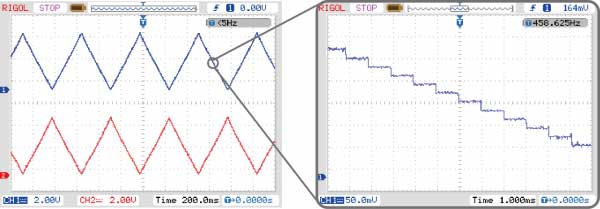
Two triangular waves out of phase can be observed from the oscilloscope. If we zoom in a section of the wave, the triangular wave is actually made up of many steps. Each steps correspond to one wiper position. The width of the step is about 1ms, because the program delay for 1ms between every wiper changes. The upstairs half cycle and the downstairs half cycle consist of 256 steps each, therefore the period of the triangular wave is 256*2=512ms. The digital pot can quickly change the wiper position and the settling time can up to micro seconds (18μs, typical).
This breakout employs MCP42100 internally manufactured with two individual 100K digital pot. It features as small dimension and low power consumption. With our tutorial and sample code provided, you can quickly apply this module to your project. Compared to the traditional mechanical potentiometer, the digital pot features as flexible (program control), small size (ICs) and high reliability (without mechanical parts). It can replace the tradition one in many applications. Digital pot is usually used to change the sound volume in audio devices, such as smart loudspeaker, cell phone, and music player.
In addition, with a proper design op-amp circuit, the digital pot can also be applied to change some key parameters of the circuit dynamically, such as LED DC dimming (output current), linear stable voltage source (output voltage), oscillator (frequency and amplitude), low pass filter (bandwidth) and differential amplifier (gain).This breakout employs MCP42100 internally manufactured with two individual 100K digital pot POT0 and POT1. Each pot has 256 taps with a resistor of 100KΩ. It supports wide voltage supply (DC 2.7V - 5.5V) compatible with MCU of 3.3V and 5V. The breakout features as small size (20.0mm*18.0mm) and reserves the SO pin for multiple breakouts being configured in daisy-chain connection. If you have a I/O shield in hand, this breakout can be easily connected to it with the attached 5 pin male to male cable.
Arduino Connection Diagram
FEATURES
- Low power, small dimension
- Dual Digital Potentiometer
- Compatible with 3.3V or 5.0V power supply
APPLICATIONS
- Sound volume or tone tuning
- LED DC dimmer, contrast control
- Programmable voltage source, filter, differential amplifier
SPECIFICATION
- Supply Voltage: 2.7~5.5V DC
- Static Operation Current: < 1 μA
- Potentiometer Value: 100 KΩ
- Resolution: 8 bits,256 taps for each potentiometer
- Number of Potentiometers: 2
- Interface: SPI
- Operation Temperature: -40℃~85℃
- Dimension: 20.0mm*18.0mm
DOCUMENTS
Jargon buster
Plain-language definitions for the technical terms used above.
- breakout
- A breakout board carries a small or fine-pitched component and brings its connections out to standard, breadboard- and header-friendly pins. Describing a part as a breakout means it can be wired into a project without soldering directly to the component's tiny contacts.
- DC
- DC means direct current, where electricity flows in one constant direction, as supplied by batteries, USB ports and many plug-pack power supplies. When a product specifies DC, it runs from a DC supply rather than mains AC, so you need to provide the correct voltage and polarity.
- LED
- A light-emitting diode (LED) is a small electronic component that emits light when current flows through it in the correct direction. Because it only conducts one way, its polarity matters, and a through-hole LED must be soldered the correct way around to light up.
- Op-amp
- An op-amp, or operational amplifier, is a chip used to amplify, buffer, or compare analogue signals. Resistor values around an op-amp help set gain and input behaviour, so choosing the right resistance matters for stable circuit performance.
- potentiometer
- A variable resistor usually turned with a knob or shaft to create an adjustable electrical signal. It is often used for inputs such as volume, brightness or position, so it helps beginners learn how a microcontroller reads changing values.
- Shield
- An add-on board that plugs into a main controller board to give it extra features such as sensing, motor control or communication. Knowing a product supports shields helps you judge whether it can connect neatly into an existing maker-board setup.
- SPI
- A fast serial communication bus often used for displays, memory cards, and sensors. It matters because SPI devices need specific pins for clock and data, plus a separate chip-select line for each device.
Find this product in
Components
Supplier page — dfrobot.com
Supplier Description · 566.9 KB · Click any page to view full size
DFR0520 mcp42100 100k dimension 1.0
Mechanical Drawings · 55.8 KB · Click any page to view full size
DFR0520 mcp42100 100k schematics 1.0
Schematic · 82.7 KB · Click any page to view full size
Related Tutorials
Free guides on learn.littlebird.com.au

