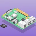
The Adafruit DC & Stepper Motor HAT drives up to 4 DC motors or 2 stepper motors from your Raspberry Pi, with full PWM speed control. It uses a dedicated PWM driver chip over I2C, so only two pins (SDA/SCL) are needed — leaving the rest free for other I2C devices or HATs.
The TB6612 MOSFET motor drivers provide 1.2A per channel (3A peak for ~20ms), a significant improvement over older L293D-based drivers. Built-in flyback diodes and a polarity-protection FET keep your Pi and HAT safe. A small prototyping area is included for additional circuitry.
Key Features
-
4× H-Bridge Motor Drivers – TB6612 chipset, 1.2A per bridge with thermal shutdown and kickback protection
-
Up to 4 DC Motors – Bi-directional with individual 8-bit PWM speed control
-
Up to 2 Stepper Motors – Unipolar or bipolar, single/double coil, interleaved, or micro-stepping
-
4.5–13.5V Motor Power – Polarity-protected 2-pin terminal block with jumper
-
I2C Control – Dedicated PWM chip, sharable bus with other I2C devices
-
Stackable – Up to 32 HATs for controlling up to 128 DC motors or 64 steppers (stacking header sold separately)
-
Prototyping Area – Extra space for custom circuitry
Also Available
Programming
- Python (pip-installable library with examples)
Compatibility
- Any Raspberry Pi with 2×20 GPIO header (A+, B+, Pi 2, Pi 3, Pi 4, Pi 5, Zero)
Important: Raspberry Pi, motors, and power supply are not included. A 5–12V DC power source is required for the motor power input.
Package Contents
- 1× Adafruit DC & Stepper Motor HAT (assembled and tested)
- Terminal blocks
- 1× 2×20 plain header (soldering required)
Note: This is a mini kit — some soldering is required to attach the header and terminal blocks. Terminal block colour may vary (blue or black).
Jargon buster
Plain-language definitions for the technical terms used above.
- DC
-
DC means direct current, where electricity flows in one constant direction, as supplied by batteries, USB ports and many plug-pack power supplies. When a product specifies DC, it runs from a DC supply rather than mains AC, so you need to provide the correct voltage and polarity.
- GPIO
-
General-purpose input/output pins are microcontroller pins you can set in software to read signals, switch devices on and off, or connect to peripherals. The number of GPIO pins matters because it limits how many buttons, LEDs, sensors, and other parts you can wire directly to the board.
- I2C
-
I2C is a two-wire communication bus used by many sensors and small modules. It matters because several I2C devices can share the same two wires, but each device needs a compatible address and your controller must support I2C.
- PWM
-
Pulse Width Modulation is a way for a digital pin to simulate variable output power by switching on and off very quickly. It matters for controlling things like LED brightness, motor speed, or servo-style signals from a microcontroller pin.
- SDA/SCL
-
SDA and SCL are the two signal lines used by an I2C bus: data and clock. Seeing these names helps you identify the correct connections when wiring I2C devices, even though Qwiic cables usually hide that wiring for you.
- Terminal block
-
A terminal block is a connector that joins wires together in a neat, removable, or serviceable way, usually clamping each wire under a screw or spring instead of soldering. It makes it easier to connect, change, or service wiring without permanent joints.