

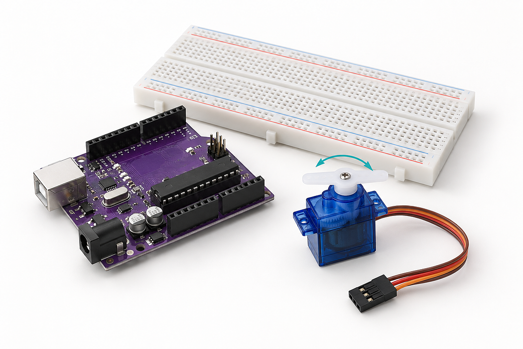
Control a continuous servo
An interactive 3D build with a live HTML servo controller and Arduino code.
Control a small continuous-rotation servo from your browser. Learn how power, ground and a timed signal work together, then experiment with speed, stopping and reversing.
This build uses USB power through the Uno’s 5V pin for an unloaded demonstration. Keep the horn clear and unplug USB before changing connections. If the Uno resets or the motor struggles, unplug it and stop.
Step 1 — Watch the complete build
Press Play for the narrated build, or follow one connection at a time below. Drag the 3D view to inspect it; scroll to zoom. Keep USB disconnected until the wiring check.
Loading assembly…
We’ll control a continuous rotation servo: change its speed, stop it, and reverse it. U S B powers this small unloaded demonstration. Keep the horn clear and leave U S B disconnected while wiring. Connect ground on the Uno to the lower negative rail with a black jumper. This rail gives the circuit a shared return path, so the servo and controller have the same reference. Connect five volts on the Uno to the lower positive rail with a red jumper. The two rails stay separate: one carries power, and the other returns to ground. This is a continuous rotation servo, so we control speed and direction rather than an angle. Its cable has three leads: brown is ground, red is power, and orange is the signal. Connect the servo’s brown ground lead to the lower negative rail with a black jumper. Its male end fits the servo’s female socket. The rail completes the return path to the Uno. Connect the servo’s red lead to the lower positive rail. That completes the five volt power path from the Uno. Leave the motor unloaded for this U S B-powered demonstration. Connect digital pin nine to the servo’s orange signal lead. The Servo library sends timed pulses along this wire; their length tells the servo which direction to turn and how fast. Check the red and black connections before adding power. Connect the square U S B plug to the Uno, then the other end to your computer. Upload the program in the editor below. Start with a modest positive speed and hold Run. Release it to stop. Now try a negative speed to reverse direction. If the horn creeps at zero, adjust the neutral setting in small steps.
Step 2 — Meet the build
We’ll control a continuous rotation servo: change its speed, stop it, and reverse it. USB powers this small unloaded demonstration. Keep the horn clear and leave USB disconnected while wiring.
Loading assembly…
We’ll control a continuous rotation servo: change its speed, stop it, and reverse it. U S B powers this small unloaded demonstration. Keep the horn clear and leave U S B disconnected while wiring.
Step 3 — See the hidden breadboard connections
The cutaway below explains the metal connections hidden inside the plastic. The terminal strips are shown in two colours to distinguish the two sides; those colours do not assign power or ground.
In this build, each rail joins the listed contacts along one side. The opposite rail does not connect automatically. If your board has a split rail, bridge the two sections only after checking which holes belong together. Never bridge positive to negative.
| From | To | Wire |
|---|---|---|
| Uno 5V | Lower + rail, hole 5 | Red |
| Uno GND | Lower − rail, hole 5 | Black |
| Servo brown/black | Lower − rail, hole 42 | Black jumper |
| Servo red | Lower + rail, hole 41 | Red |
| Uno D9 | Servo orange/yellow signal | Orange |
Step 4 — Connect the ground rail
Connect ground on the Uno to the lower negative rail with a black jumper. This rail gives the circuit a shared return path, so the servo and controller have the same reference.
Loading assembly…
Connect ground on the Uno to the lower negative rail with a black jumper. This rail gives the circuit a shared return path, so the servo and controller have the same reference.
Step 5 — Connect the power rail
Connect five volts on the Uno to the lower positive rail with a red jumper. The two rails stay separate: one carries power, and the other returns to ground.
Loading assembly…
Connect five volts on the Uno to the lower positive rail with a red jumper. The two rails stay separate: one carries power, and the other returns to ground.
Step 6 — Add the continuous servo
This is a continuous rotation servo, so we control speed and direction rather than an angle. Its cable has three leads: brown is ground, red is power, and orange is the signal.
Loading assembly…
This is a continuous rotation servo, so we control speed and direction rather than an angle. Its cable has three leads: brown is ground, red is power, and orange is the signal.
Step 7 — Connect servo ground
Connect the servo’s brown ground lead to the lower negative rail with a black jumper. Its male end fits the servo’s female socket. The rail completes the return path to the Uno.
Loading assembly…
Connect the servo’s brown ground lead to the lower negative rail with a black jumper. Its male end fits the servo’s female socket. The rail completes the return path to the Uno.
Step 8 — Connect servo power
Connect the servo’s red lead to the lower positive rail. That completes the five volt power path from the Uno. Leave the motor unloaded for this USB-powered demonstration.
Loading assembly…
Connect the servo’s red lead to the lower positive rail. That completes the five volt power path from the Uno. Leave the motor unloaded for this U S B-powered demonstration.
Step 9 — Connect the control signal
Connect digital pin nine to the servo’s orange signal lead. The Servo library sends timed pulses along this wire; their length tells the servo which direction to turn and how fast.
Loading assembly…
Connect digital pin nine to the servo’s orange signal lead. The Servo library sends timed pulses along this wire; their length tells the servo which direction to turn and how fast.
Step 10 — Connect USB
Check the red and black connections before adding power. Connect the square USB plug to the Uno, then the other end to your computer. Upload the program in the editor below.
Loading assembly…
Check the red and black connections before adding power. Connect the square U S B plug to the Uno, then the other end to your computer. Upload the program in the editor below.
Step 11 — How the signal works
The Servo library sends pulse-length commands on D9. A continuous servo interprets these as speed and direction. Zero in the App means the calibrated neutral pulse, not an angle of zero degrees. Positive and negative values select opposite directions; which one looks clockwise depends on the servo and your viewing side.
The on-screen horn illustrates the command. It cannot measure the physical shaft’s speed or position.
Step 12 — Upload the Arduino program
Keep the servo unloaded and its horn clear. In Chrome or Edge, choose Pair board, select the Uno, then Verify and Upload. Wait for Ready before using the App below.
The sketch starts stopped, uses 115200 baud, and stops within one second without Run heartbeats. USB powers this demonstration through Uno 5V; the brown lead and Uno share ground.
Step 13 — Control the servo
The connection is shared with the code editor above. Set a modest speed and hold Run; release to stop. Negative values reverse the servo. If the horn creeps at zero, release Run, open Neutral calibration and adjust the neutral pulse in small increments before testing again. Power off before touching the horn or wiring.
Download the App HTML to reuse in English → App → Edit HTML. The on-screen horn follows commands; it is not position feedback.
Step 14 — Run, stop and reverse
Start with a modest positive speed and hold Run. Release it to stop. Now try a negative speed to reverse direction. If the horn creeps at zero, adjust the neutral setting in small steps.
Loading assembly…
Start with a modest positive speed and hold Run. Release it to stop. Now try a negative speed to reverse direction. If the horn creeps at zero, adjust the neutral setting in small steps.
Step 15 — Try, predict and compare
- With the horn clear and no mechanical load, choose a small positive speed such as 15 and hold Run. Expect slow continuous rotation.
- Release Run. Expect the motor to stop. Try −15 and compare the direction.
- Return to zero. If the horn creeps, release Run and adjust Neutral calibration by a few microseconds. Retest until stationary.
- Compare 15 and 30. The number is a command percentage, not a measured RPM; twice the setting need not produce exactly twice the speed.
Step 16 — Troubleshoot your build
| What you see | What to check |
|---|---|
| No movement | Wait for Ready after upload, select a nonzero speed, and hold Run. Check D9 and the shared ground. |
| Creeps at zero | Trim neutral in small increments; do not force the horn by hand. |
| Uno resets, motor stutters or struggles | Unplug USB and stop. This unloaded demonstration may exceed a particular USB source’s available current. A larger load needs a correctly rated external motor supply with common ground; do not tie its positive output to Uno 5V. |
| Rotates to an angle and stops | Check the part: this lesson requires a continuous-rotation servo, not a positional SG90. |
The program starts stopped and stops after one second without Run heartbeats. Disconnect USB before changing wiring.
Parts List
Required Parts (4)
Continuous rotation; speed and direction rather than an angle.
x1
$8.20
In stock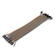
Optional Extras (1)
Additional USB data cable; use an existing one if available.
Optional$2.00
Project Summary
5 parts total
Unavailable items will be skipped
