

Control a servo with distance
An interactive 3D build with a live HTML servo controller and Arduino code.
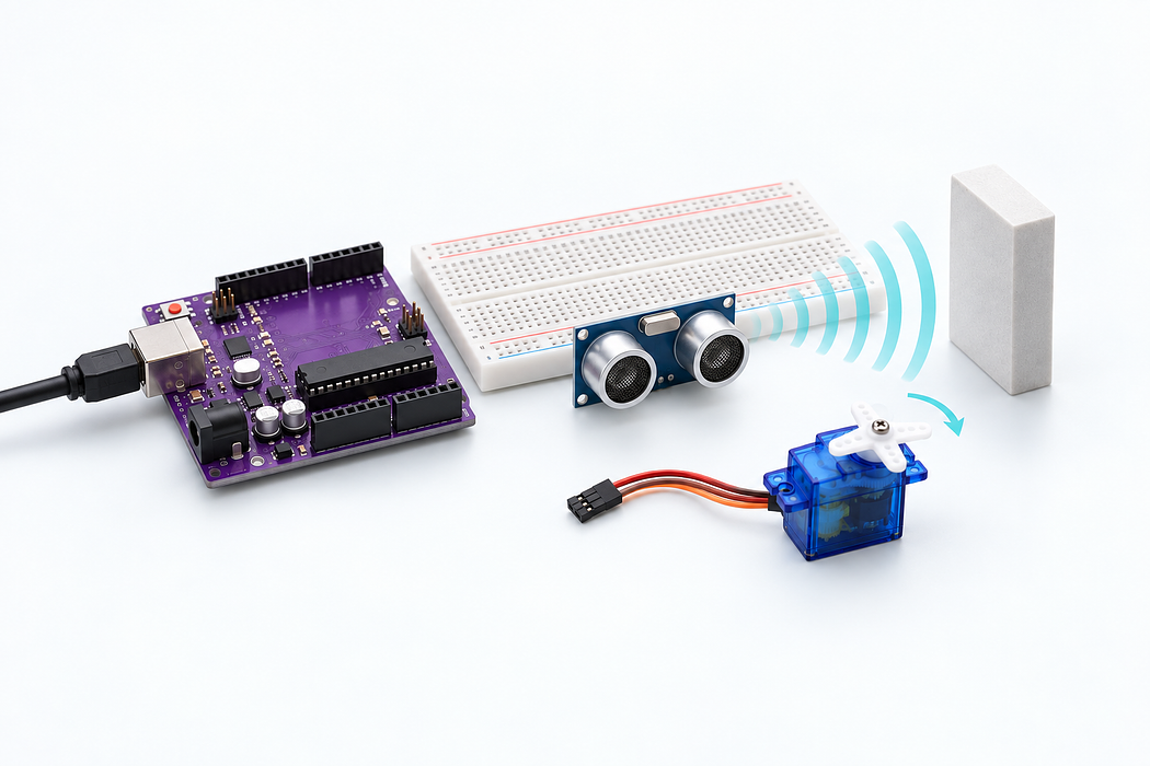
Build a distance-controlled continuous rotation servo with the Little Bird Uno and a full-size breadboard. Move a flat object towards the sensor to slow and stop the servo.
This demonstration uses USB power through the Uno’s 5V pin. Keep the small servo unloaded and its horn clear. Disconnect USB before changing wires. If the Uno resets or the servo struggles, unplug USB and stop the test.
Step 1 — Watch the complete build
Press Play for the narrated build. Drag the view to explore in 3D, or follow the individual steps below.
Loading assembly…
We’re making a distance-controlled servo. Move an object closer to slow it down, or further away to speed it up. This unloaded demonstration uses U S B power through the Uno. Leave U S B disconnected while wiring. Connect five volts from the Uno to the upper positive rail, and ground to the upper negative rail. These shared connections will supply both the sensor and the servo. This ultrasonic sensor measures distance using its two silver transducers. Face them towards the object you want to detect, with the four header pins accessible for the jumper wires. Connect the sensor’s power pin to the upper positive rail, then its ground pin to the upper negative rail. Red carries five volts; black provides the return to ground. Connect digital pin seven to trigger, then digital pin six to echo. The Uno sends a brief trigger pulse and times the returning echo to work out the distance. This servo turns continuously. Our program controls its speed and direction, rather than choosing an angle. Keep the horn clear so the motor can turn freely during this demonstration. Connect the servo’s red power lead to the upper positive rail. Connect its brown or black ground lead to the lower negative rail. The remaining lead carries the control signal. Join the upper and lower negative rails with a black jumper. That completes the servo’s return path to the Uno, so the sensor, servo and controller share the same ground. Connect digital pin nine to the servo’s signal lead. The Servo library sends timed pulses: around fifteen hundred microseconds stops the motor, while shorter or longer pulses change its speed and direction. Check the wiring, then connect U S B to the Uno and upload the program below. Keep the servo unloaded. If the board resets or the motor struggles, unplug U S B and stop the test. Choose distance sensor mode and hold Run. Bring an object closer to slow the servo; at fifteen centimetres it stops. Move away to speed up again. Release Run to stop the motor.
Step 2 — Meet the build
We’re making a distance-controlled servo. Move an object closer to slow it down, or further away to speed it up. This unloaded demonstration uses USB power through the Uno. Leave USB disconnected while wiring.
Loading assembly…
We’re making a distance-controlled servo. Move an object closer to slow it down, or further away to speed it up. This unloaded demonstration uses U S B power through the Uno. Leave U S B disconnected while wiring.
Step 3 — Prepare the rails
Connect five volts from the Uno to the upper positive rail, and ground to the upper negative rail. These shared connections will supply both the sensor and the servo.
Loading assembly…
Connect five volts from the Uno to the upper positive rail, and ground to the upper negative rail. These shared connections will supply both the sensor and the servo.
Step 4 — Add the distance sensor
This ultrasonic sensor measures distance using its two silver transducers. Face them towards the object you want to detect, with the four header pins accessible for the jumper wires.
Loading assembly…
This ultrasonic sensor measures distance using its two silver transducers. Face them towards the object you want to detect, with the four header pins accessible for the jumper wires.
Step 5 — Power the sensor
Connect the sensor’s power pin to the upper positive rail, then its ground pin to the upper negative rail. Red carries five volts; black provides the return to ground.
Loading assembly…
Connect the sensor’s power pin to the upper positive rail, then its ground pin to the upper negative rail. Red carries five volts; black provides the return to ground.
Step 6 — Connect trigger and echo
Connect digital pin seven to trigger, then digital pin six to echo. The Uno sends a brief trigger pulse and times the returning echo to work out the distance.
Loading assembly…
Connect digital pin seven to trigger, then digital pin six to echo. The Uno sends a brief trigger pulse and times the returning echo to work out the distance.
Step 7 — Add the continuous servo
This servo turns continuously. Our program controls its speed and direction, rather than choosing an angle. Keep the horn clear so the motor can turn freely during this demonstration.
Loading assembly…
This servo turns continuously. Our program controls its speed and direction, rather than choosing an angle. Keep the horn clear so the motor can turn freely during this demonstration.
Step 8 — Connect the servo cable
Connect the servo’s red power lead to the upper positive rail. Connect its brown or black ground lead to the lower negative rail. The remaining lead carries the control signal.
Loading assembly…
Connect the servo’s red power lead to the upper positive rail. Connect its brown or black ground lead to the lower negative rail. The remaining lead carries the control signal.
Step 9 — Share a common ground
Join the upper and lower negative rails with a black jumper. That completes the servo’s return path to the Uno, so the sensor, servo and controller share the same ground.
Loading assembly…
Join the upper and lower negative rails with a black jumper. That completes the servo’s return path to the Uno, so the sensor, servo and controller share the same ground.
Step 10 — Connect the control signal
Connect digital pin nine to the servo’s signal lead. The Servo library sends timed pulses: around fifteen hundred microseconds stops the motor, while shorter or longer pulses change its speed and direction.
Loading assembly…
Connect digital pin nine to the servo’s signal lead. The Servo library sends timed pulses: around fifteen hundred microseconds stops the motor, while shorter or longer pulses change its speed and direction.
Step 11 — Connect USB and upload
Check the wiring, then connect USB to the Uno and upload the program below. Keep the servo unloaded. If the board resets or the motor struggles, unplug USB and stop the test.
Loading assembly…
Check the wiring, then connect U S B to the Uno and upload the program below. Keep the servo unloaded. If the board resets or the motor struggles, unplug U S B and stop the test.
Step 12 — Upload the Arduino program
Keep the servo unloaded. Pair the Uno in Chrome or Edge, choose Arduino Uno, then Verify and Upload. The App HTML is already loaded under the App tab. After upload, wait for Ready before pressing Run.
The sketch starts stopped and uses 115200 baud. Without Run heartbeats it stops within one second. USB supplies this demonstration through the Uno’s 5V pin; all components share ground.
Step 13 — Control the servo with distance
The connection is shared with the code editor above. Set a modest speed and hold Run; release to stop. Negative values reverse the servo. Choose Distance sensor to slow down from 60 cm to 15 cm and stop at 15 cm or on a missing echo. If the horn creeps at zero, release Run, open Neutral calibration and adjust the neutral pulse in small increments before testing again. Power off before touching the horn or wiring.
Download the App HTML to reuse in English → App → Edit HTML. The on-screen horn follows commands; it is not position feedback.
Step 14 — Try distance control
Choose distance sensor mode and hold Run. Bring an object closer to slow the servo; at fifteen centimetres it stops. Move away to speed up again. Release Run to stop the motor.
Loading assembly…
Choose distance sensor mode and hold Run. Bring an object closer to slow the servo; at fifteen centimetres it stops. Move away to speed up again. Release Run to stop the motor.
Step 15 — Plot the readings
View distance and commanded speed on the same shared serial connection. Click legend entries to hide channels you do not need. Distance is −1 when no valid echo is received. Hold Run in the App while experimenting; changing guide steps releases the control and stops the servo.
Parts List
Required Parts (6)
Continuous rotation; speed and direction rather than an angle.
x1
$8.20
In stock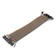

Optional Extras (1)
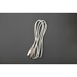
Additional USB data cable; use an existing one if available.
Optional$2.00
Project Summary
7 parts total
Unavailable items will be skipped
