Little Bird
Learn to solder kit - Flashing LED
This small soldering kit is a fun practice project for anyone building confidence with through-hole soldering. Once assembled, the LEDs flash across the boar...
Get notified when back in stock
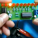
This small soldering kit is a fun practice project for anyone building confidence with through-hole soldering. Once assembled, the LEDs flash across the board in sequence, creating a simple running-light effect.
The flash speed can be adjusted by turning the potentiometer, making it a satisfying hands-on circuit to build and test. The design uses an NE555 self-excited multivibrator to generate the clock signal and a CD4017 decimal counter to step through the LEDs.
A power supply is not included, and the kit needs a 3-5V input. Printed instructions are not included, but a video tutorial is available to follow along with during assembly.
Features:
- Fun beginner soldering project for practising soldering skills.
- LEDs flash across the board in sequence.
- Flash speed can be changed by turning the potentiometer.
- Uses an NE555 multivibrator circuit and CD4017 decimal counter circuit.
- Creates a water-light effect with D1 - D10 sequentially lit.
- Power supply is not included.
- Requires an input of 3-5v.
- Video tutorial available for assembly guidance.
Specifications:
- Power supply voltage: 3-5V
- PCB Size: 88 x 25mm
- Instructions: Not included
- Charging time: 0.695 (R2 + R3 + R4) C1
- Discharge time: 0.695 (R4 + R3) C1
Great for classrooms, makerspaces, or anyone wanting a simple electronics kit to practise soldering and see an immediate visual result.
Jargon buster
Plain-language definitions for the technical terms used above.
- PCB
- A printed circuit board (PCB) is a board, usually rigid, with etched copper tracks that connect electronic components together without loose wiring. Components are mounted on the board and signals route between them through the copper layout.
- potentiometer
- A variable resistor usually turned with a knob or shaft to create an adjustable electrical signal. It is often used for inputs such as volume, brightness or position, so it helps beginners learn how a microcontroller reads changing values.
- through-hole
- A mounting style where the component leads pass through holes in a circuit board and are soldered on the other side. Through-hole parts are often easier to handle and solder by hand, which is useful for classroom and hobby projects.
Find this product in
Components
Tutorials & Links
Guides, forum threads and other useful pages elsewhere on the web
Project Guides
Step-by-step builds that use this part