

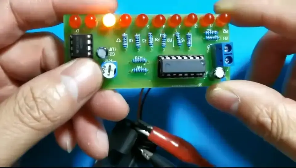
Assembling the flashing LED learn-to-solder kit
Build the ten-LED chaser in our Learn to Solder kit step by step — resistors first, then the IC sockets, LEDs, speed trimmer and the NE555/CD4017 — and get it chasing on 3 V.
What you’re building
Ten red LEDs chase along a row, and a little trimmer sets how fast they run. It is the classic first soldering project — about forty through-hole joints, nothing surface-mount, and nothing that will let the smoke out if you take your time.
How the circuit works
The NE555 timer and the parts around it form an astable oscillator — a square-wave generator. Its output on pin 3 feeds the clock input of the CD4017 decade counter. Every pulse moves the counter’s single high output one step along Q0–Q9, lighting the LED on that output and turning the previous one off. Ten outputs, ten LEDs, one chase. Turning the R13 trimmer changes the oscillator frequency, which is the chase speed.
Tools you’ll need
- A soldering iron and solder. Use decent solder — cheap solder will not flow properly and leaves dry joints that come back to haunt you.
- Side cutters, for trimming leads flush.
- A 2×AA battery box (3 V) or any 3–5 V supply.
- A small flat screwdriver, if you are using the screw terminal rather than soldering the leads on.
What’s in the kit
| Qty | Part | Position | How to identify it |
|---|---|---|---|
| 10 | 1 kΩ resistor | R1–R10 | brown-black-red-gold (4-band) or brown-black-black-brown-brown (5-band) |
| 1 | 2.2 kΩ resistor | R11 | red-red-black-brown-brown — look for the two red bands |
| 1 | 10 kΩ resistor | R12 | brown-black-orange-gold (4-band) or brown-black-black-red-brown (5-band) |
| 1 | 50 kΩ trimmer | R13 | blue square trimmer marked 503 — sets the chase speed |
| 1 | NE555 timer IC | U1 | 8 pins, notch at one end |
| 1 | CD4017 decade counter IC | U2 | 16 pins, notch at one end |
| 1 | 8-pin IC socket | U1 | notch at one end |
| 1 | 16-pin IC socket | U2 | notch at one end |
| 10 | Red LED | D1–D10 | polarised — long leg is positive |
| 2 | 1 µF electrolytic capacitor | C1, C2 | polarised — white stripe marks the negative leg |
| 1 | Screw terminal block | J1 | power input, 3–5 V |
| 1 | PCB | — | silkscreen revision 592249W_Y3-241028 |
Check everything off against this list before you pick up the iron. If something is missing, sort that out first — it is far more annoying to discover halfway through.
Four rules that save the build
- Shortest parts first. Resistors, then IC sockets, then LEDs, then the trimmer, terminal and capacitors. Low parts stay flat against the board when you turn it over to solder.
- Watch the polarised parts. LEDs (long leg into the + hole), electrolytic capacitors (long leg positive, white stripe negative) and both ICs (notch to notch). Resistors and the trimmer do not care which way round they go.
- Inspect after every pass. Every pad actually soldered, joints full and rounded rather than starved, no dry joints, and no solder bridged between neighbouring pads.
- Sockets, not chips. Solder the IC sockets and push the NE555 and CD4017 in at the very end. Heat and ICs do not mix.
If it doesn’t work
| Symptom | What to check |
|---|---|
| Nothing lights at all | Supply polarity (VCC positive, GND negative), battery voltage, and that both ICs are the right way round and fully seated |
| Some LEDs never light | That LED’s polarity — the long leg must be in the + hole — and a dry joint on its two pads |
| Erratic chasing, or no chasing | NE555 and CD4017 fully home in their sockets with no pin folded underneath, capacitor polarity, dry joints |
| Board gets warm, or looks dead short | Solder bridges between adjacent pads — inspect the back under a light and separate any that have run together |
Step 1 — Start with the ten 1 kΩ resistors
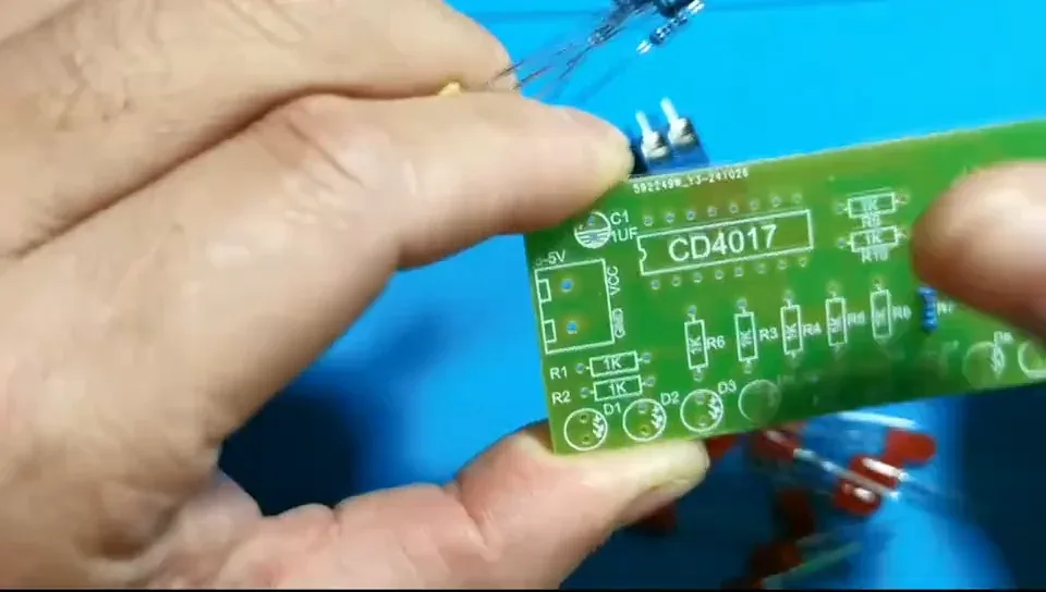
Work shortest-part-first, so the resistors go in before anything else. Ten 1 kΩ resistors fill R1–R10 — the silkscreen prints 1K at each position.
Colour code: brown-black-red-gold (4-band) or brown-black-black-brown-brown (5-band).
Step 2 — Resistors aren't polarised
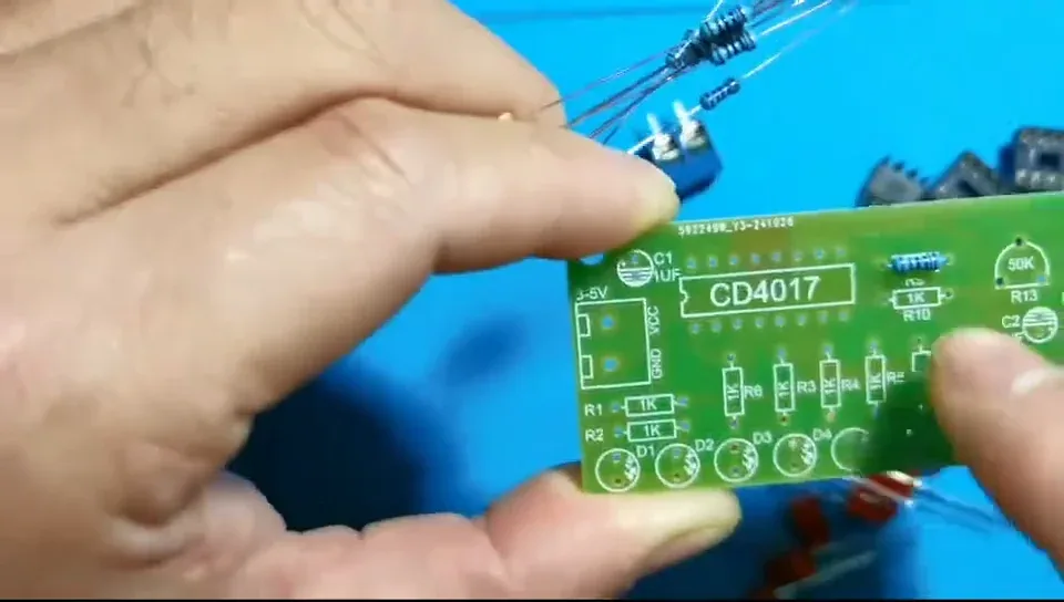
There is no right way round — push the legs through whichever way they fall.
Only the LEDs, the two electrolytic capacitors and the two ICs care about orientation.
Step 3 — Splay the legs to hold each one in place
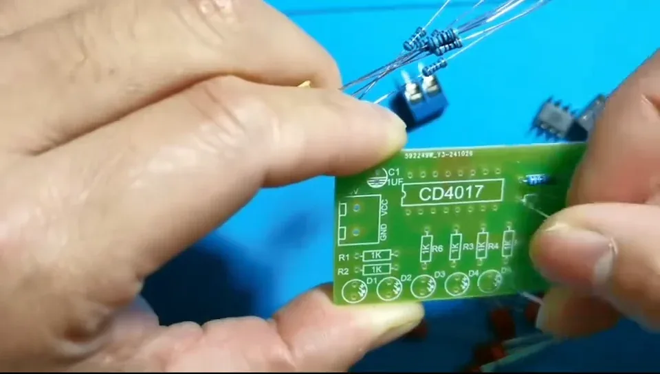
Bend the two legs outwards underneath the board. The resistor then stays put — and stays flat — when you turn the board over to solder.
Step 4 — Push each resistor flat against the board
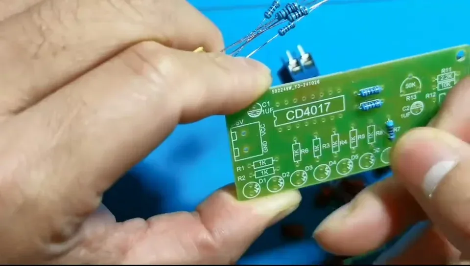
Seat the body right down on the PCB. A resistor left standing proud looks untidy and gets in the way of the LED row later.
Step 5 — Work steadily along the row
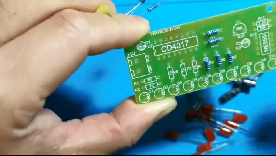
Each 1 kΩ resistor is the current-limiting resistor for one LED, so they run in a line between the LED positions and the CD4017 socket.
Step 6 — Check you've got a 1 kΩ, not the odd one out
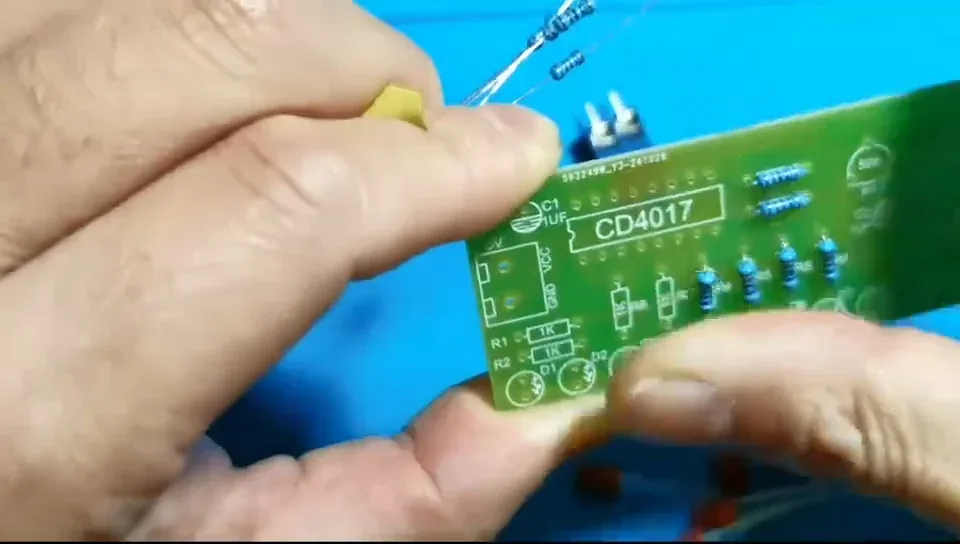
The bag also holds one 2.2 kΩ and one 10 kΩ. If you spot two red bands, that is the 2.2 kΩ — put it aside for R11.
Step 7 — Fit them all before you pick up the iron
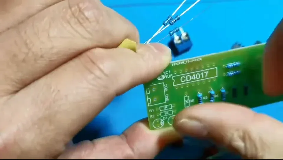
It is far quicker to load the whole board and then solder in one pass than to solder each part as it goes in.
Step 8 — Face the colour bands the same way
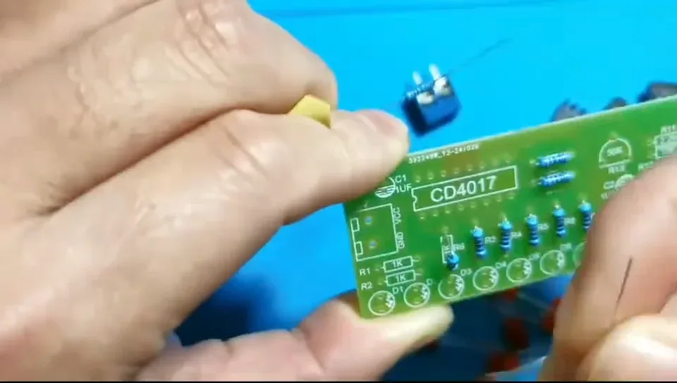
Purely cosmetic, but lining up the gold tolerance bands makes the finished board look properly built — and makes the values easy to re-read later.
Step 9 — Nine down, one to go
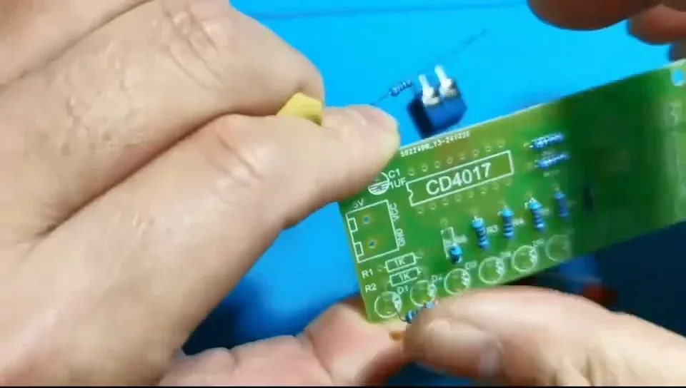
Count as you go. There should be exactly ten 1 kΩ resistors — one for each of D1–D10.
Step 10 — Fit the tenth 1 kΩ resistor
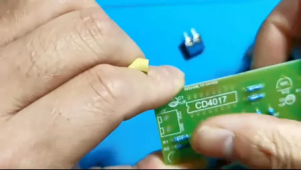
That is all ten current-limiting resistors in. Only the 2.2 kΩ and the 10 kΩ are left.
Step 11 — All ten 1 kΩ resistors in place
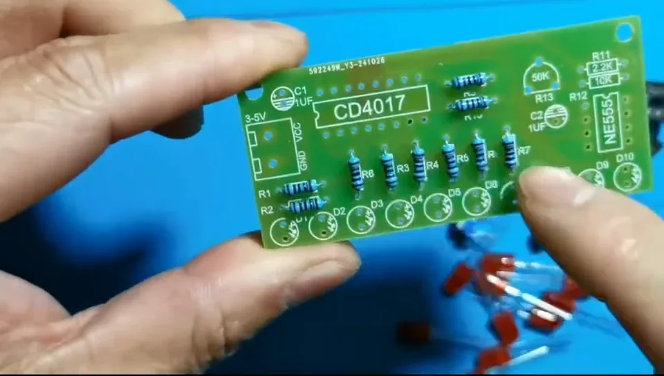
Take a moment to check every 1K position is filled and that nothing is sitting crooked or proud of the board.
R11, R12 and R13 up in the top corner are still empty.
Step 12 — Pick out the 2.2 kΩ resistor
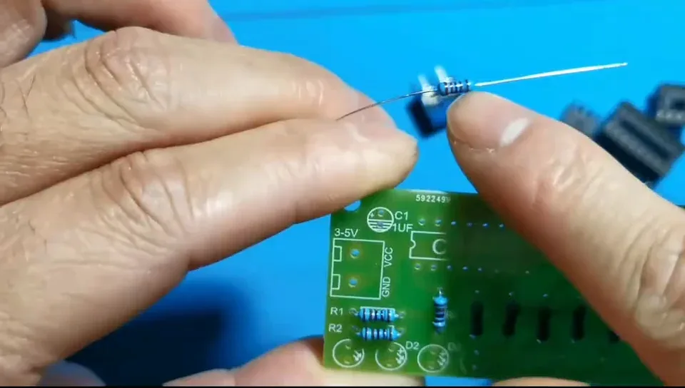
Identify it by its two red bands — the full 5-band code is red-red-black-brown-brown. It is the only resistor of that value in the kit, and it goes at R11.
Step 13 — Fit the 2.2 kΩ at R11 and the 10 kΩ at R12
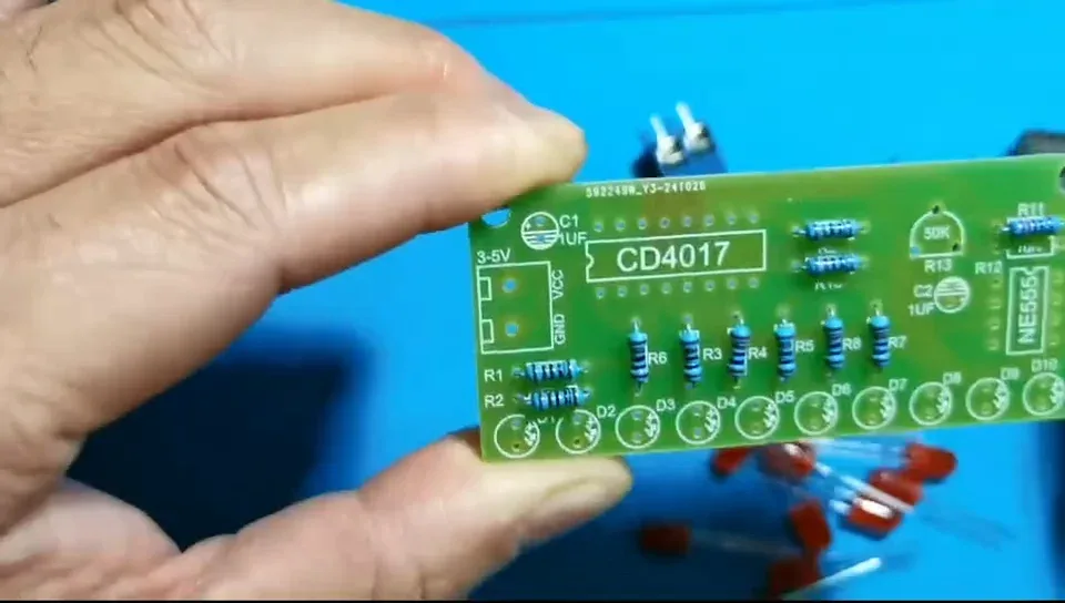
The 10 kΩ reads brown-black-orange-gold (4-band) or brown-black-black-red-brown (5-band).
These two set the NE555's timing, so they must go in their own holes — don't swap them.
Step 14 — Seat everything flat before you solder
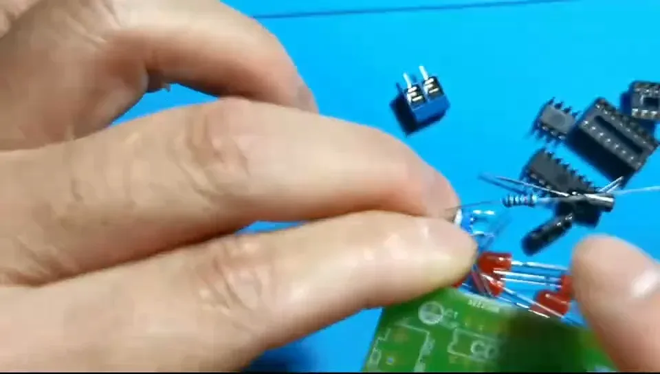
Run a finger along the row and press down anything that has lifted. Twelve resistors should now be fitted: ten 1 kΩ, one 2.2 kΩ and one 10 kΩ.
Step 15 — Last look at the front of the board
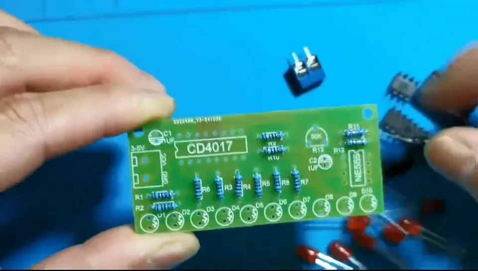
Every silkscreened resistor position should be filled. What's left in the bag is the trimmer, the LEDs, the capacitors, the two sockets, the two chips and the screw terminal.
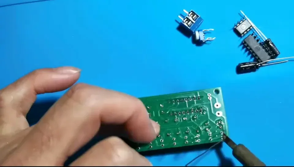
Step 16 — Solder every resistor joint
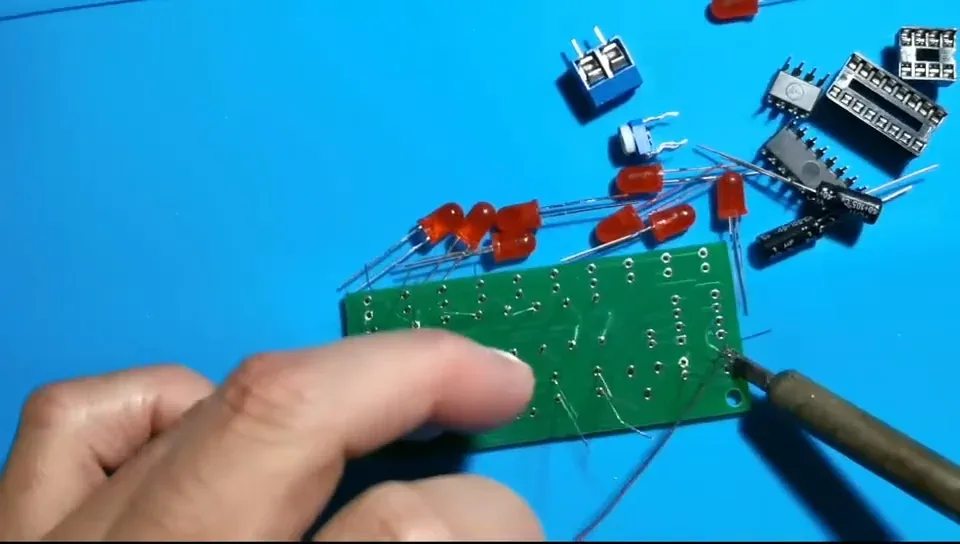
Flip the board and solder all twenty-four pads.
Use decent solder. Poor-quality solder won't flow properly and leaves dry joints that are a nightmare to find later.
Step 17 — Trim the legs and inspect
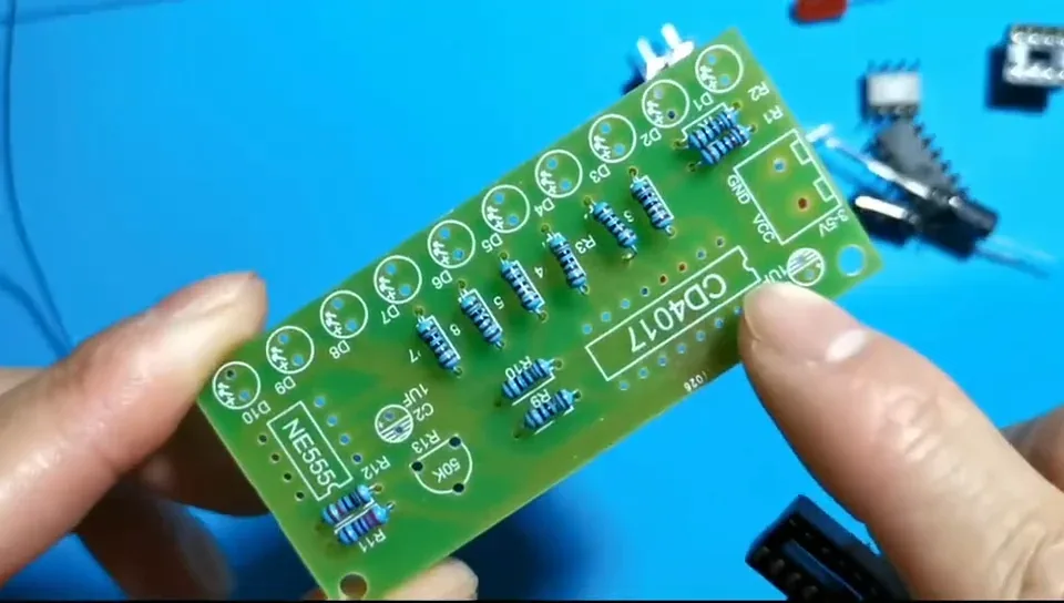
Snip the leads flush with each joint, then check: every pad soldered, joints full and rounded rather than starved, and no solder bridged between neighbouring pads.
Step 18 — Drop in the 16-pin socket for the CD4017
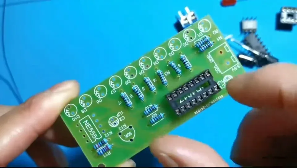
Fit the socket, not the chip. The socket keeps the CD4017 well away from soldering heat, and lets you swap it out if you ever need to.
Step 19 — Line the socket notch up with the board
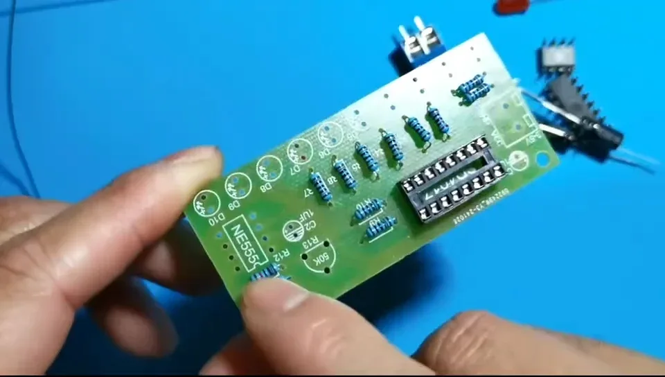
Both the socket and the silkscreen outline have a notch at one end. Notch to notch.
Get this right now and the chip can only go in one way later.
Step 20 — Fit the 8-pin socket for the NE555
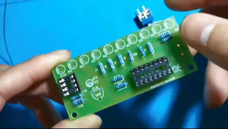
Same rule: the notch on the 8-pin socket lines up with the notch printed at the NE555 position, over by D10.
Step 21 — Solder the socket pins
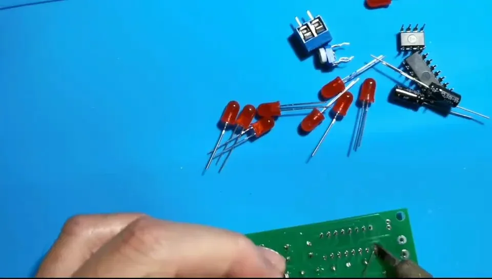
Tack one corner pin of each socket first, check the socket is still sitting flat on the board, then solder the rest.
A socket that lifts at one end looks awful and strains its joints.
Step 22 — Check the back before moving on
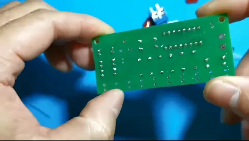
Socket pins sit close together, so this is where bridges happen. Adjacent pads must never be joined — if two joints have run together, separate them now.
Step 23 — Get the ten LEDs ready
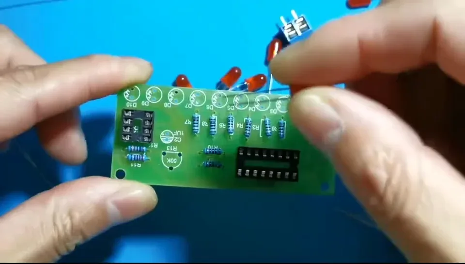
LEDs are polarised. The long leg is positive (the anode); the short leg is negative.
Every LED position on the board is marked with a + on the lower side. The long leg goes in that hole.
Step 24 — Fit the first LED at D1
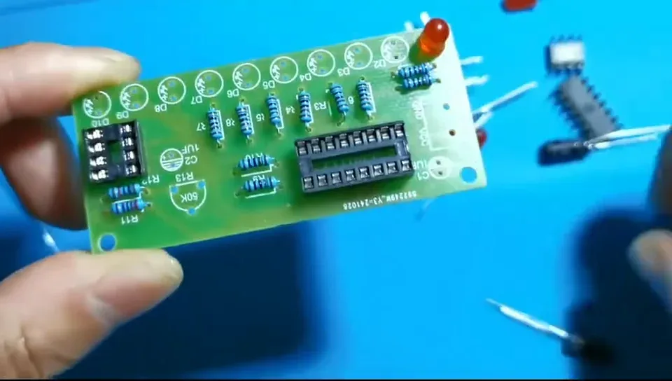
Long leg into the + hole. Get this wrong and that LED simply will not light.
Step 25 — Fit D2 the same way round
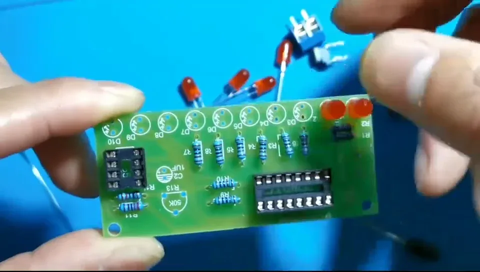
All ten LEDs face the same way — every long leg goes into the hole on the lower side of the board.
Step 26 — Fit D3
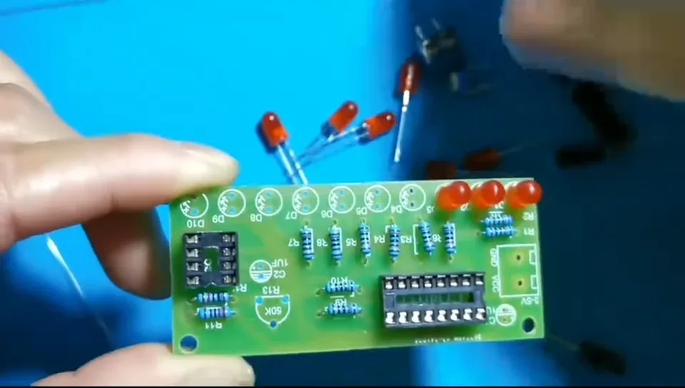
Push each LED down until it is sitting on the board. You will straighten the row properly once one leg of each is tacked.
Step 27 — Fit D4
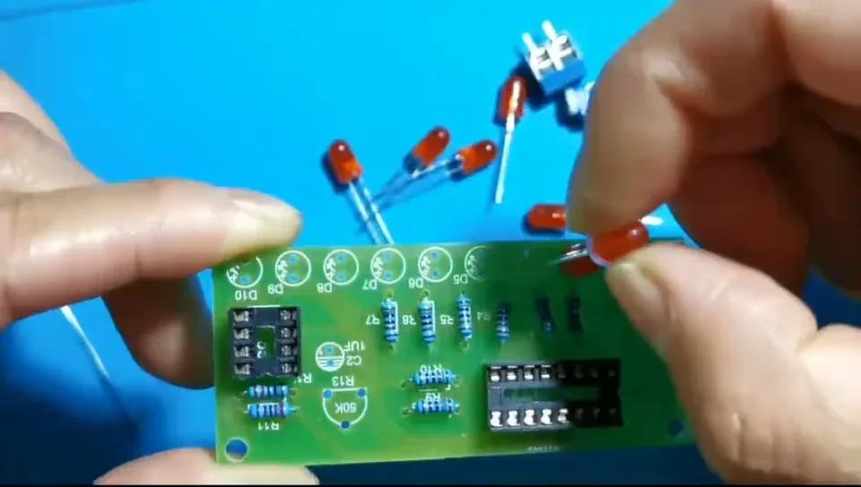
If you can't tell which leg is longer, hold the LED up against one you have already fitted and compare.
Step 28 — Fit D5 — halfway
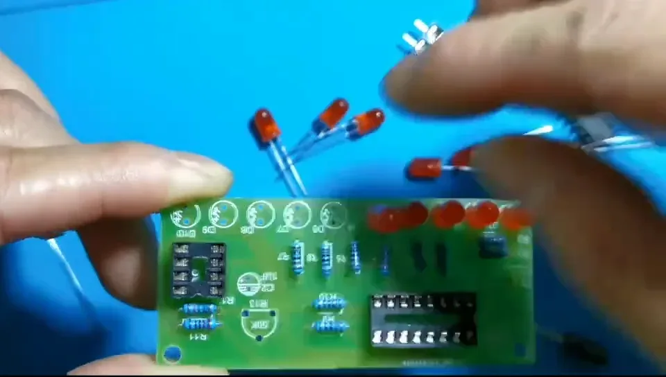
The chase runs D1 → D10 in order, so a single LED in backwards shows up straight away when you power the board on.
Step 29 — Fit D6
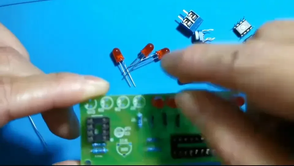
Keep the legs splayed underneath so the LEDs don't drop out when you turn the board over.
Step 30 — Fit D7
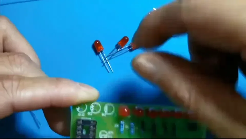
Don't trim anything yet. Those long legs are what let you nudge each LED straight in a moment.
Step 31 — Fit D8
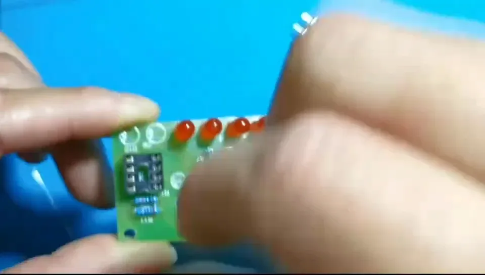
Two to go. Glance along the row from the side now and then — the LEDs should all be standing at roughly the same height.
Step 32 — Fit D9
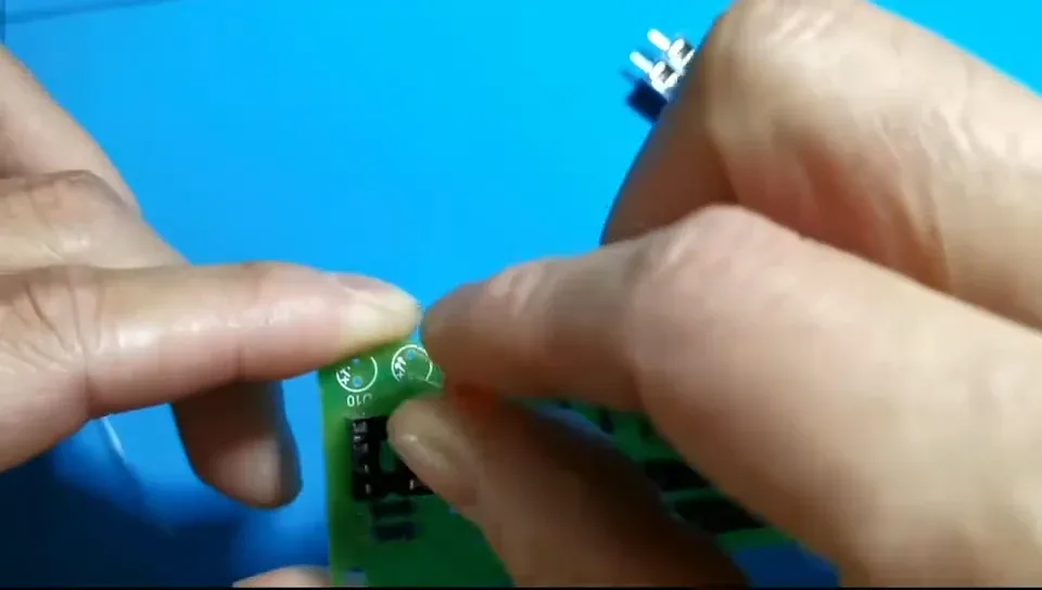
Long leg into the + hole, same as the other eight.
Step 33 — Fit the last LED at D10
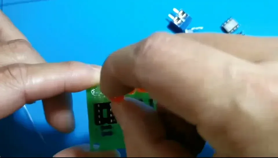
D10 sits at the end of the row nearest the NE555 socket. That's all ten in.
Step 34 — Check every LED before you solder
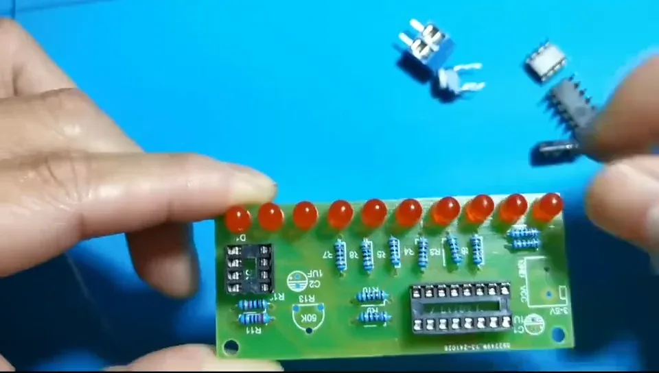
Look down the row: all ten long legs should be on the same side of the board.
It is much easier to fix a reversed LED now than after it is soldered and trimmed.
Step 35 — Turn the board over
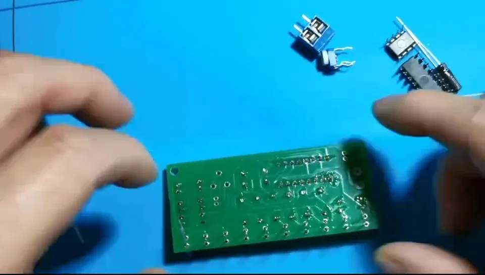
Support the LEDs with your fingers as you flip it so nothing drops out.
Step 36 — Solder just ONE leg of each LED
This is the trick to a tidy row. With only one leg tacked you can still reheat that single joint and move the LED.
Step 37 — Straighten the row, then solder the second legs
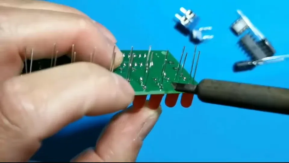
Even out the spacing and push down any LED sitting too high, re-melting its one joint as you go.
When the row looks right, solder the second leg of every LED and trim the legs flush.
Step 38 — Check the back again
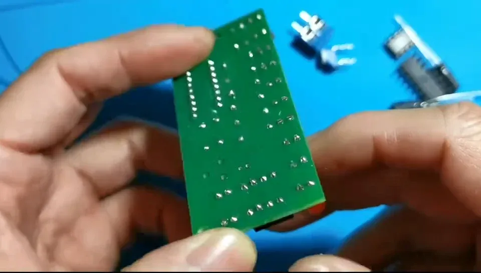
Twenty more joints to look over. No dry joints, no bridges — then move on.
Step 39 — Pick up the potentiometer
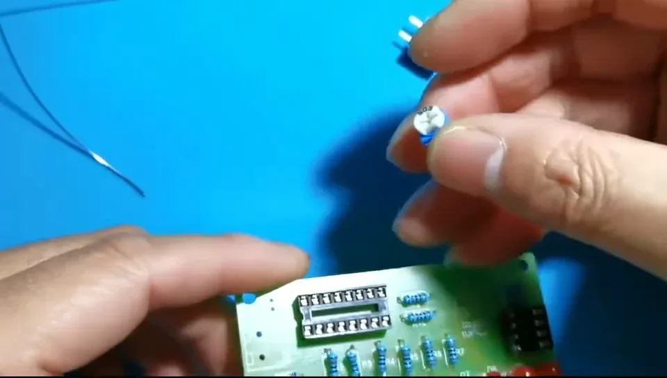
The little blue trimmer, marked 503 (50 kΩ), is R13. It sets the NE555's frequency — which is the chase speed.
Step 40 — Find the R13 position
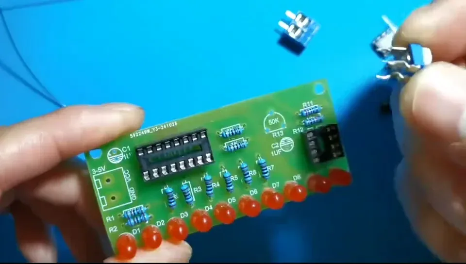
R13 is the three-hole footprint next to C2, marked 50K on the silkscreen.
Step 41 — Push the trimmer in — it only fits one way
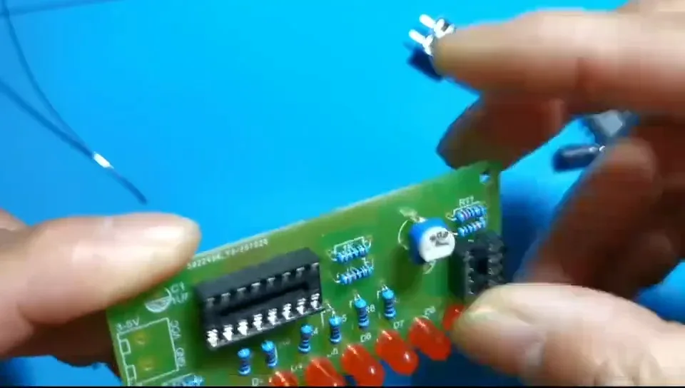
Three pins, three holes, and the spacing means it can only drop in one way round. No polarity to worry about here.
Step 42 — Seat the trimmer flat
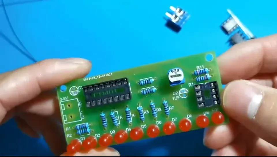
Press it down until the body touches the board before you solder, so the adjusting screw ends up square to the PCB and easy to reach.
Step 43 — Position the screw terminal on the 3–5 V pads
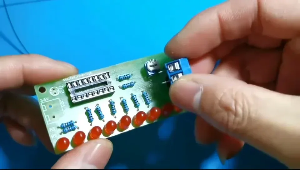
This is the power input, J1, on the end of the board marked 3-5V. It takes anything from 3 V to 5 V.
Step 44 — Point the wire openings outwards
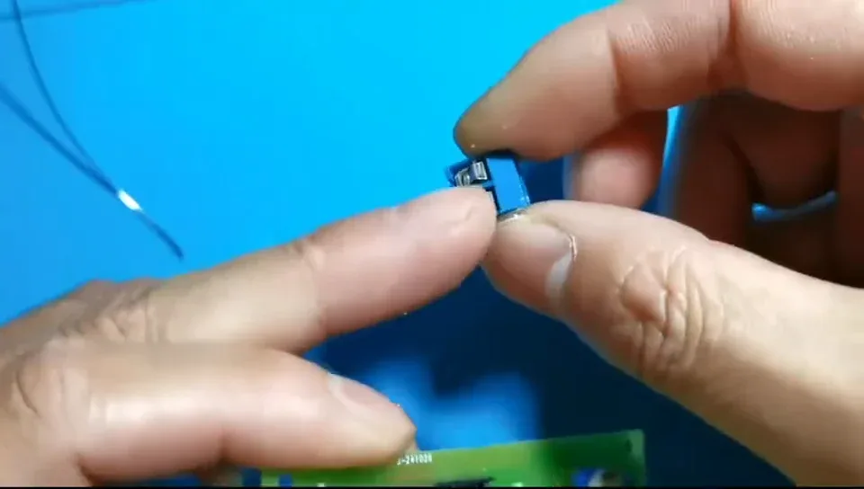
Fit the terminal so the metal face — the holes you feed the wires into — points off the edge of the board.
Turned inwards, you can't get a wire or a screwdriver to it.
Step 45 — Press the terminal flat against the board
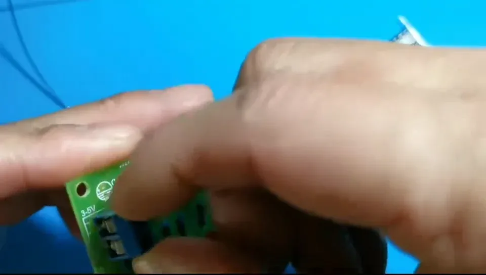
It is a chunky part, so hold it down while you tack the first pin, then solder the second.
Step 46 — Solder the trimmer and the terminal
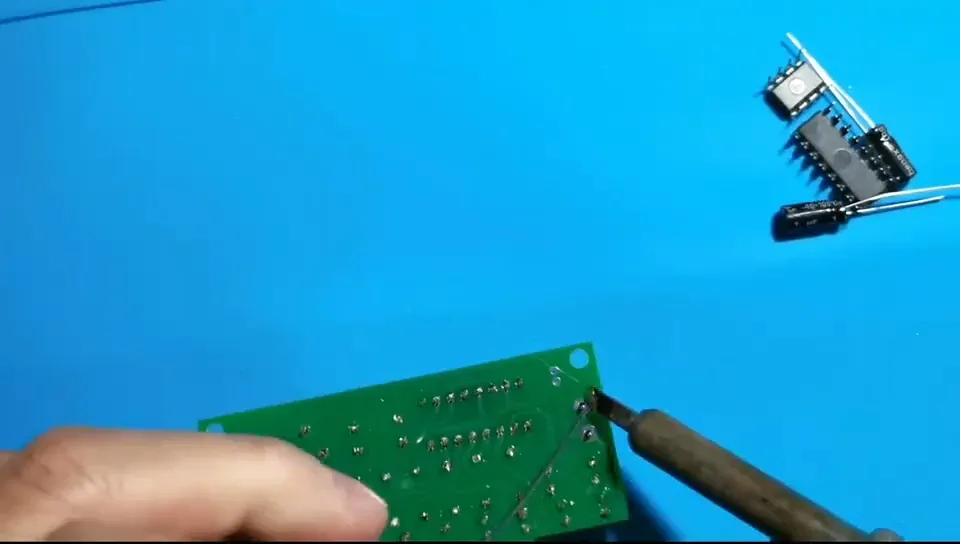
Board over, solder all five joints, and give them the same once-over as everything else.
Step 47 — Pick up the first electrolytic capacitor
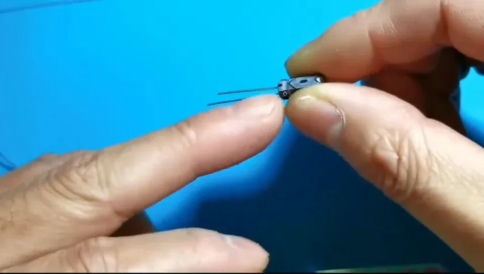
There are two 1 µF electrolytics in the kit, C1 and C2. Unlike the resistors, these are polarised.
Step 48 — Work out which leg is which
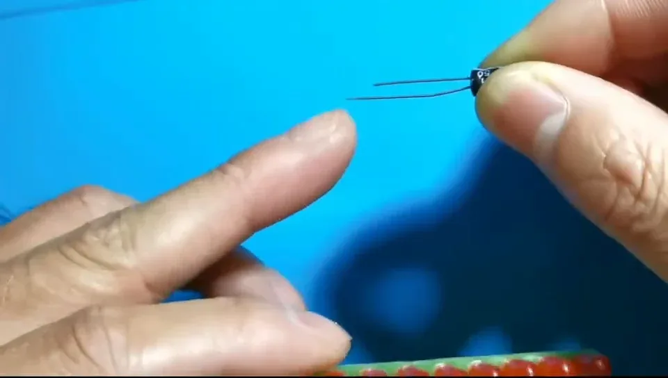
Long leg = positive, short leg = negative.
The white stripe down the side of the can marks the negative leg — that's your double-check.
Step 49 — Fit C2
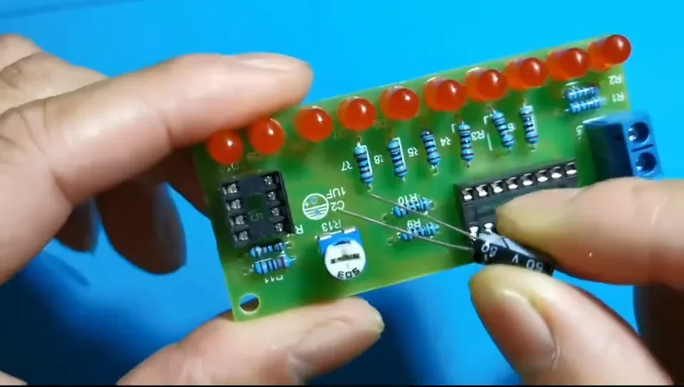
On the PCB each capacitor position has a + for positive and a shaded marking for negative.
On this board both capacitors go the same way: positive towards the lower side, negative towards the top.
Step 50 — Push C2 down flat
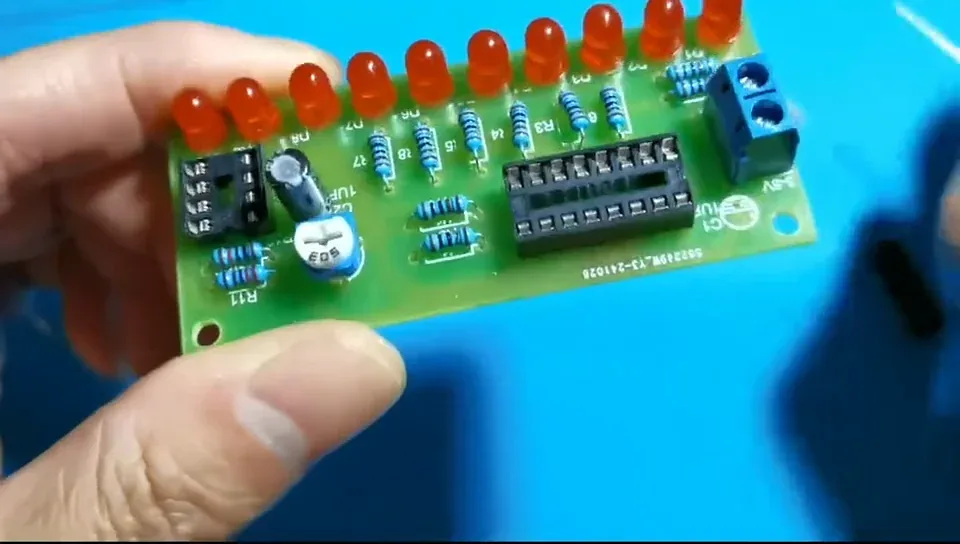
Get the can sitting on the board. A reversed electrolytic can vent or fail, so this is the one part worth checking twice.
Step 51 — Fit C1
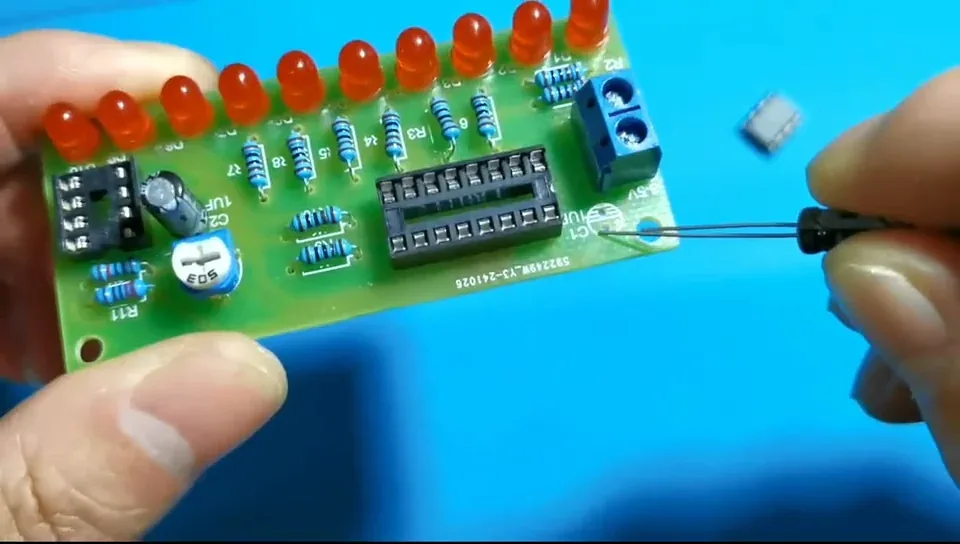
Same orientation as C2 — long leg into the + hole, white stripe towards the top edge. C1 sits beside the screw terminal.
Step 52 — Both capacitors in
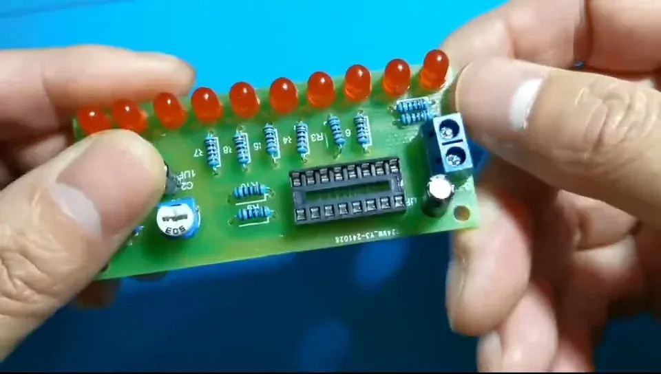
Check both against the silkscreen one last time before you turn the board over. Positive to the +, striped side to the shaded marking.
Step 53 — Turn the board over one more time
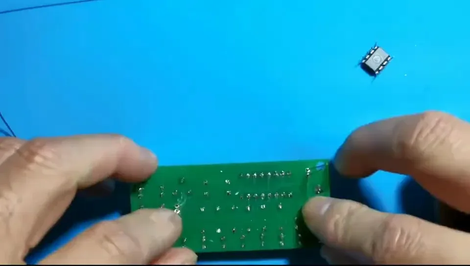
Only the two capacitors are left to solder. The chips just push into their sockets afterwards — no heat involved.
Step 54 — Solder the capacitors and trim
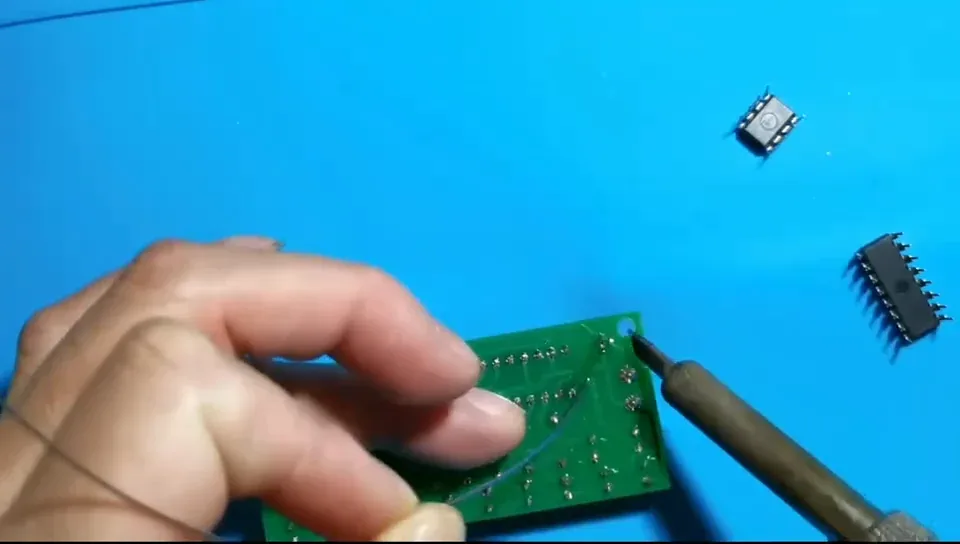
Four joints, then inspect for dry joints and bridges and snip the legs flush.
That's the soldering finished.
Step 55 — Pick up the NE555
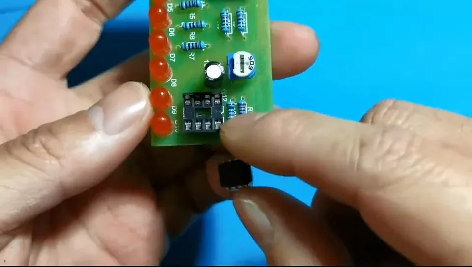
The 8-pin chip is the NE555 timer, U1 — the oscillator that drives the whole thing.
Step 56 — Match the chip's notch to the socket's notch
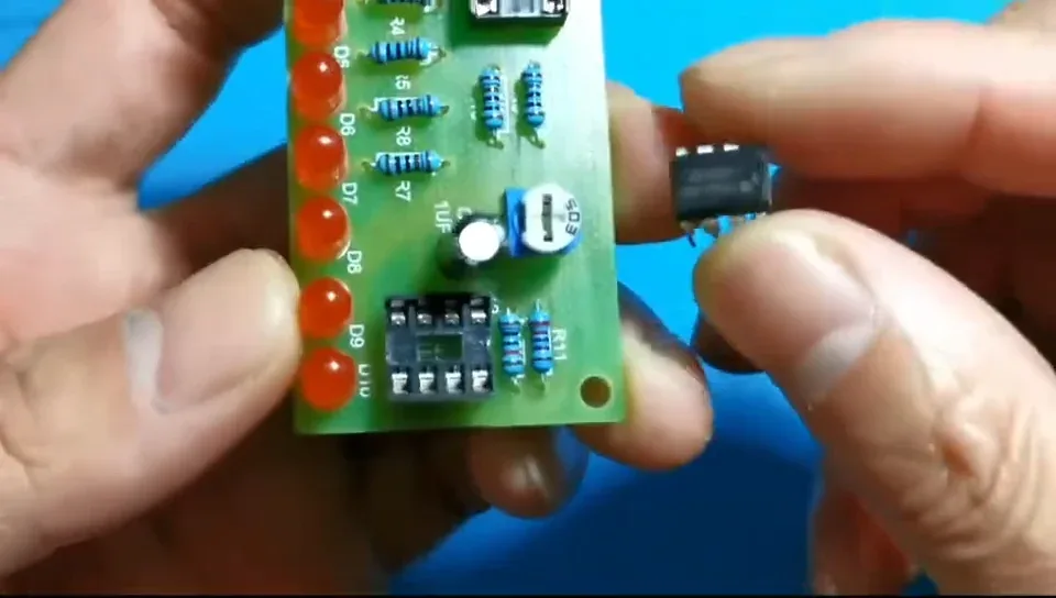
The NE555 has a notch (and usually a dot) at one end. On this board the notch faces downwards — the same way as the socket you soldered in.
Step 57 — Straighten the pins first
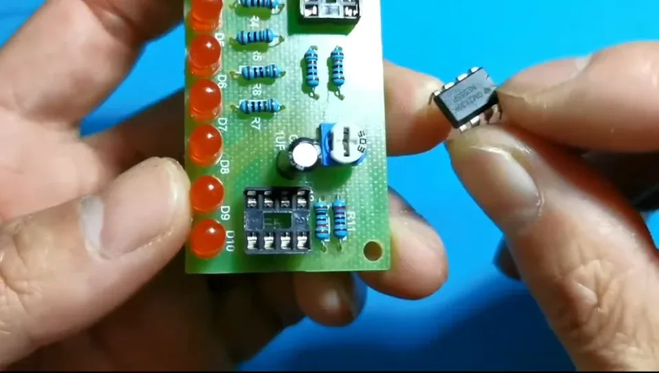
If the two rows are splayed outwards, roll them gently against a flat surface until both rows are parallel. Never force a chip into a socket.
Step 58 — Press the NE555 home
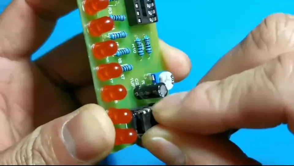
Line all eight pins up with the socket holes, check none has folded under, then push the chip down evenly with your thumb.
Step 59 — NE555 seated
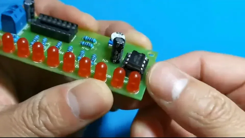
Both rows of pins should be fully home, with the chip sitting square on the socket and no gap underneath.
Step 60 — Pick up the CD4017
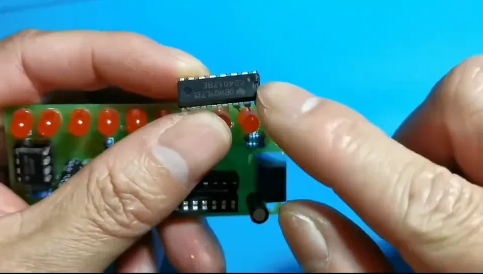
The 16-pin chip is the CD4017 decade counter, U2 — the part that steps the lit LED along the row.
Step 61 — Line the CD4017 notch up with the board
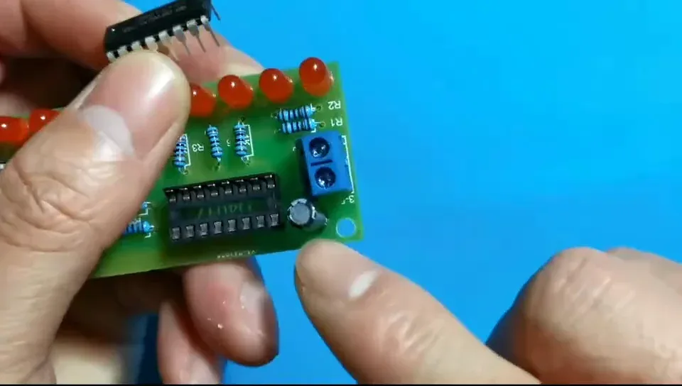
Exactly the same rule as the 555: the notch on the chip matches the notch printed on the PCB and moulded into the socket.
Step 62 — Press the CD4017 home
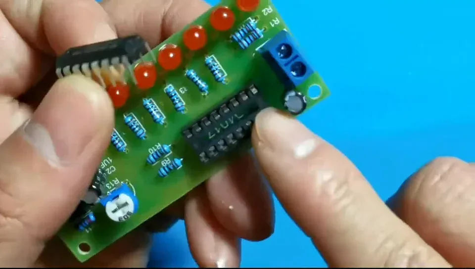
Straighten the pins, sit all sixteen in the socket holes, then push down evenly. Check the ends as well as the middle — long chips like to lift at one end.
Step 63 — Both chips fitted
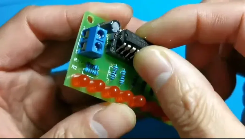
That's the build complete. Nothing left to do except connect power.
Step 64 — Look the finished board over
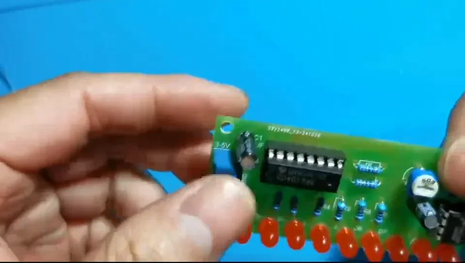
Twelve resistors, two sockets with their chips, ten LEDs, the trimmer, two capacitors and the screw terminal — and a clean back with no bridges.
Step 65 — Get the battery box ready
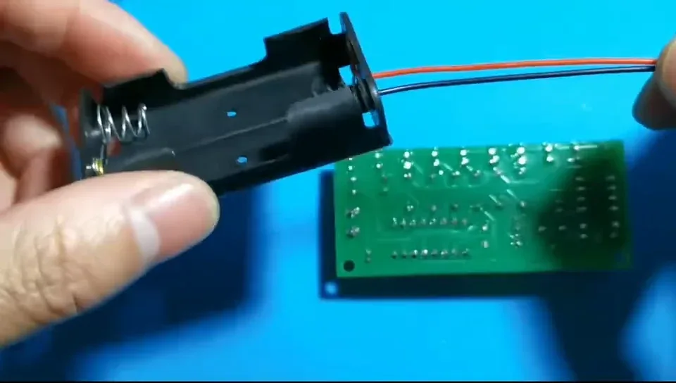
A 2×AA box gives 3 V, right in the middle of the board's 3–5 V range.
Red wire = positive. Black wire = negative.
Step 66 — Find VCC and GND on the terminal
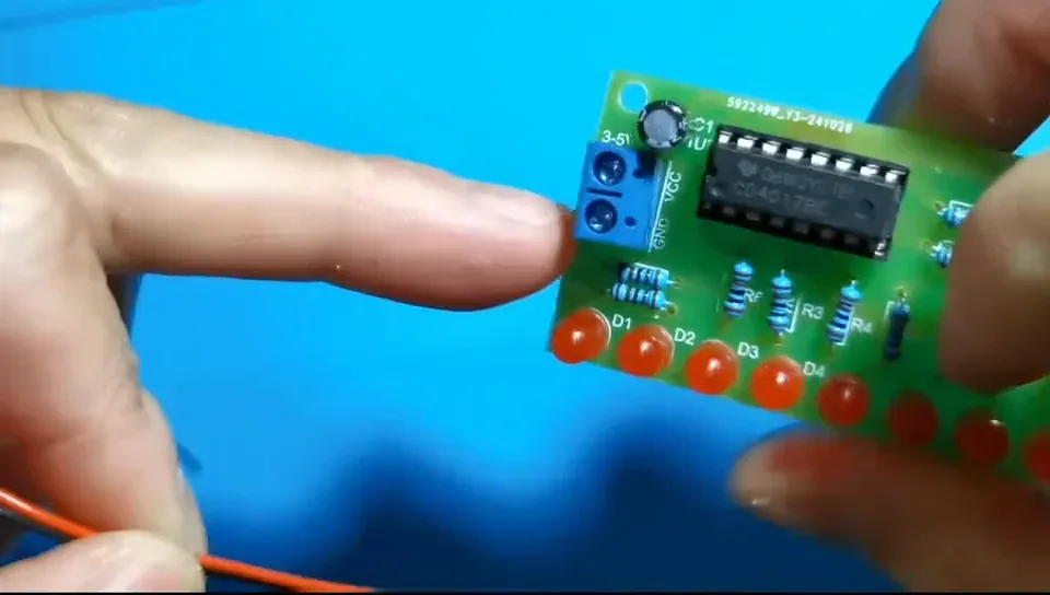
The two connections are labelled on the silkscreen right beside the terminal block: VCC and GND.
Step 67 — VCC takes the red wire
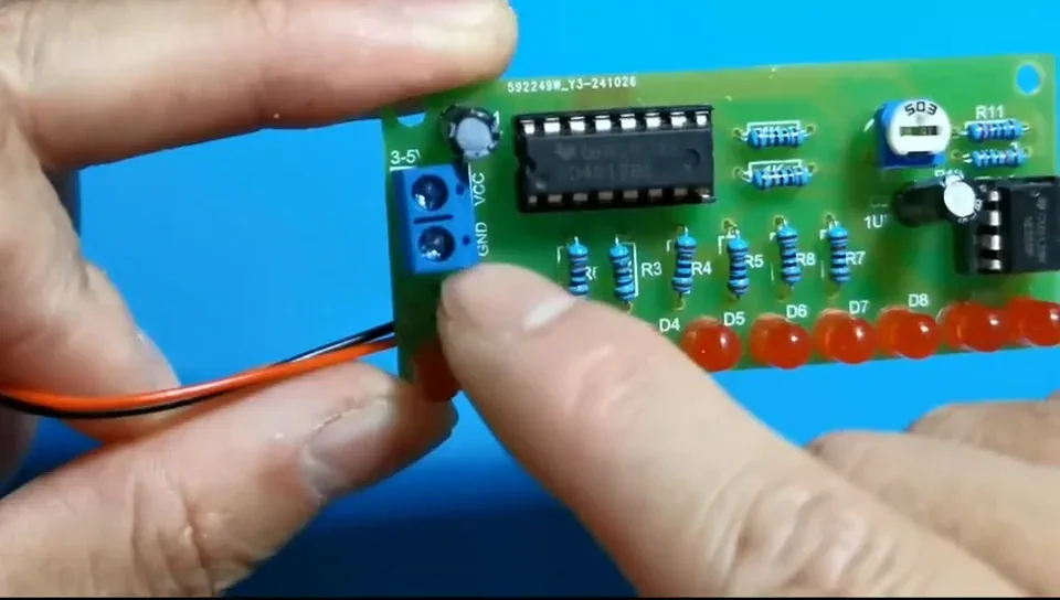
VCC is positive. Feed the red lead into that opening and tighten the screw down onto it with a small flat screwdriver.
Step 68 — GND takes the black wire
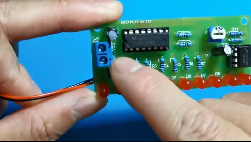
GND is negative. Swap these two over and nothing will light.
Step 69 — Or solder the leads straight to the back
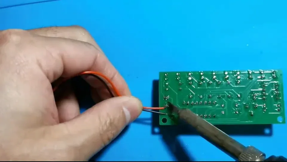
If you would rather skip the screw terminal, solder the battery leads directly to the VCC and GND pads on the back of the board. It is tidier, and it's what the video does.
Step 70 — Solder the second lead
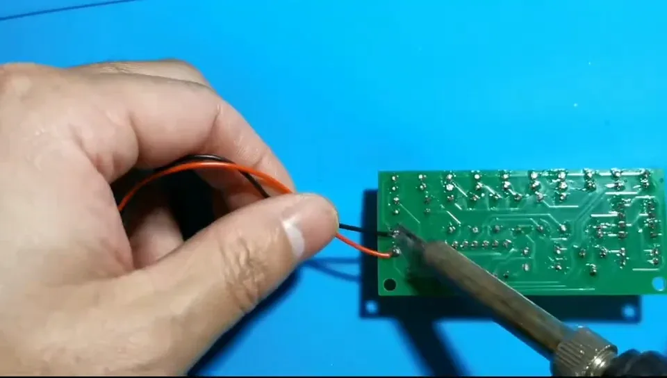
Keep the polarity the same either way: red to VCC, black to GND.
Step 71 — Check the polarity one last time
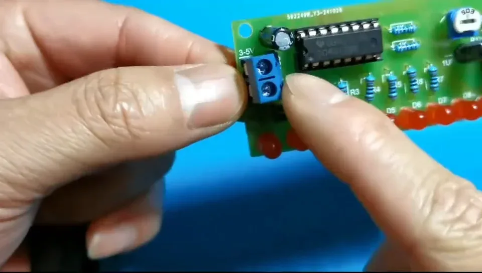
VCC positive, GND negative, 3–5 V only. This is your last chance to catch a reversed supply before the board is live.
Step 72 — Connect the battery box
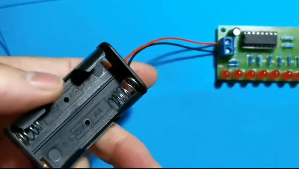
Drop the cells in and the board should come to life straight away.
Step 73 — The LEDs chase along the row
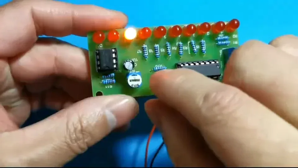
The NE555 oscillates, the CD4017 steps its output along Q0–Q9, and the lit LED runs D1 → D10 over and over.
If one LED stays dark, that one is in backwards or has a dry joint.
Step 74 — Set the speed with the trimmer
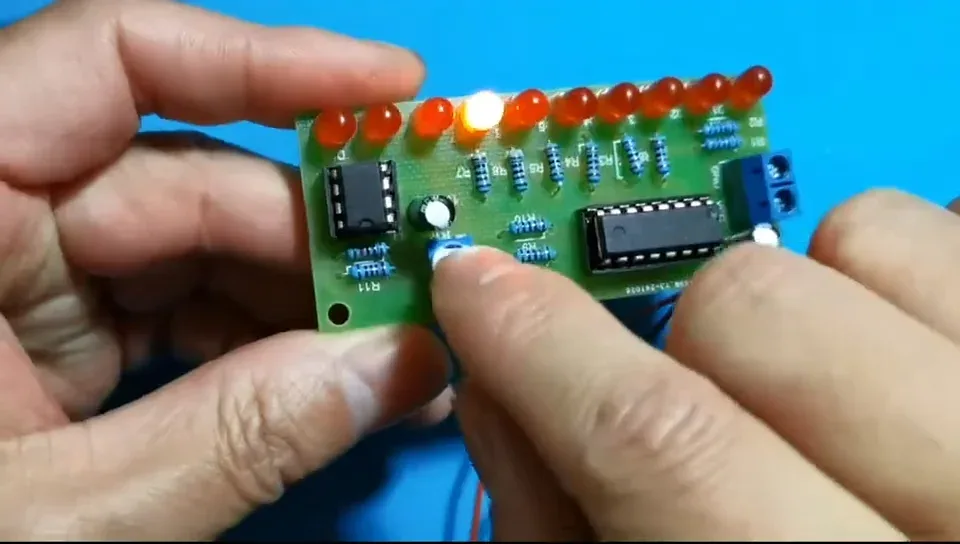
Turn R13 left to slow the chase down, right to speed it up. Wound fully clockwise gives the fastest run — which is how most people leave it.
That's the build finished. Nice work.
Parts List
Required Parts (1)
Project Summary
1 part total
Unavailable items will be skipped
