

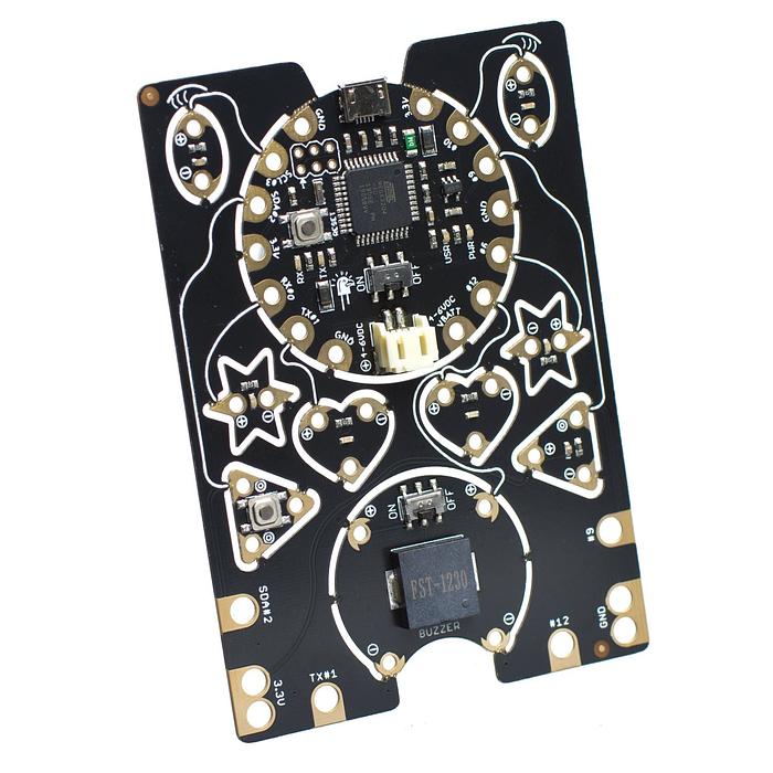
Blink an eye with EagLED
Make the right eye blink, then investigate how on-time and off-time shape a repeating signal.
Make the right eye blink, then investigate how on-time and off-time shape a repeating signal.
Designed for the intact EagLED v1.2 with buzzer. Start with USB power; no cutting or sewing is required.
Step 1 — Prepare the intact EagLED
Use an intact black EagLED v1.2 with buzzer, a micro-USB data cable and a computer. The LEDs, button and light sensor are already connected by PCB traces. You do not need jumper wires, a breadboard, external resistors or a separate Arduino.
Keep the board uncut for this project. Place it on a dry, non-conductive surface. Leave the battery socket empty, connect USB and move the main board switch to ON. Move the separate switch beside the buzzer to OFF for quiet LED and sensor experiments.
The 3D view follows this starter program and its controls. It illustrates the mechanism; it does not execute changes made in the code editor or measure a connected board.
Step 2 — Explore the result in 3D
Press Play to see the right red eye (D10) on for half a second and off for half a second. On your board, observe at least five complete cycles. Drag to orbit, inspect a named component, and use Top or Underside to follow the real board layout.
Step 3 — Program your EagLED
The English IDE below opens with Little Bird EagLED and Arduino C++ selected. Read the English instructions beside the supplied program, then press Verify to compile it for this board.
To program your physical board, download the same sketch below and open it in Arduino IDE. Install the Little Bird AVR board package, choose Little Bird EagLED and its USB port, then Verify and Upload. Follow the EagLED setup guide if this is your first upload. Upload replaces the factory light pattern.
EagLED uses an ATmega32U4 at 8 MHz. Do not choose Uno or a 16 MHz Leonardo profile. Its USB port can change while the bootloader is active. If upload fails, check the selected port and retry after pressing the centre board’s reset button. The triangular project button is not reset. Close any browser serial connection before uploading from Arduino IDE.
Step 4 — Keep a copy of the complete program
const byte EYE_PIN = 10;
const unsigned long ON_MS = 500;
const unsigned long OFF_MS = 500;
void setup() { pinMode(EYE_PIN, OUTPUT); }
void loop() {
  digitalWrite(EYE_PIN, HIGH);
  delay(ON_MS);
  digitalWrite(EYE_PIN, LOW);
  delay(OFF_MS);
}
This is the same complete Arduino C++ program used by the English IDE. Copy it or download the .ino file.
Step 5 — Understand the program
EYE_PIN is a pin number, while ON_MS and OFF_MS are times in milliseconds. const keeps those settings fixed while the sketch runs. setup() runs once and configures the pin as an output.
digitalWrite(EYE_PIN, HIGH);
delay(ON_MS);
HIGH supplies the LED through its on-board resistor. The first delay holds that state. The following LOW command turns it off, and the second delay holds the off state. The whole loop() repeats. The full period is ON_MS + OFF_MS, not just one delay.
Step 6 — Work through one case
| Elapsed time | Command/state | Right eye |
|---|---|---|
| 0 ms | HIGH | On |
| 500 ms | LOW | Off |
| 1000 ms | Next loop: HIGH | On |
One cycle takes 1000 ms = 1 s, so the starting program blinks once per second.
Step 7 — Test it on your board
Press Play to see the right red eye (D10) on for half a second and off for half a second. On your board, observe at least five complete cycles.
Check the physical output after uploading. Successful compilation confirms syntax and board compatibility; the 3D illustration cannot confirm your board’s USB connection or electrical operation.
Step 8 — Predict, change and compare
Predict the period and on fraction if you change only ON_MS to 250. Keep OFF_MS at 500. Verify and upload; time ten cycles with a stopwatch. Record the total and divide by ten. Restore 500/500 afterwards.
Check your reasoning after trying it
The period is 750 ms and the on fraction is 250/750 = one third. Ten cycles take about 7.5 s, allowing for your reaction time. Changing one delay changes both the period and the on/off balance.
Step 9 — Find and fix a problem
The wrong LED blinks: check EYE_PIN is 10, not 7 (USR) or 3 (left eye). Only the 3D view changed: edited code must be verified and uploaded to change the real board.
Nothing responds: check the main switch, the power indicator and a known data-capable USB cable. Confirm the EagLED board profile and USB port. If the board has already been snipped apart, its original connections are broken: follow a separate sewable wiring project before using this intact-board sketch.
Step 10 — Keep exploring
Continue through the EagLED experiments or open the full board explorer. The original EagLED schematic and manufacturing files document the pin connections.
Parts List
Required Parts (1)
Keep the board intact. Also bring a micro-USB data cable and computer. No additional sensor, LED, Arduino or breadboard is required.
x1
$34.35
In stockProject Summary
1 part total
Unavailable items will be skipped
