

Turn the knob, dim the light
Scale a sensor reading and discover how fast switching controls LED brightness.
Step 1 — What you will discover
Connect input, conversion and output in one program, and distinguish an input voltage from an output switching pattern.
Predict: At halfway, will the brightness number be around 512 or 127?
Before you begin
Read a 0–1023 ADC value; know D9 supports PWM.
Your goal: Map an input to a PWM output. Show this with a prediction, a tested change and an explanation using the program’s names.
Retrieve one idea: what input, state or output did you change in the previous project?
Need a reminder? Read the knob.
Step 2 — Meet this circuit
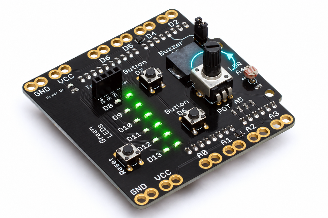
Use an Arduino Uno with the Crack the Code shield. The shield already connects its LEDs, knob, light sensor and buttons; this activity needs no jumper wires or breadboard.
If the shield is not fitted, disconnect USB power, align every shield pin with the Uno sockets, and press evenly without bending the pins. Reconnect the Uno with a USB data cable. Leave the traffic-light module disconnected for this activity.
Step 3 — Upload your program
Open the example below. Read the English plan, then choose Arduino C++ from the language selector and Arduino Uno from the board selector. Select Verify to compile. Select Pair board…, choose the Uno’s serial port, then select Upload. Use Chrome or Edge on a desktop computer with this HTTPS page for browser upload. If browser upload is unavailable, copy the complete C++ sketch into Arduino IDE, choose Arduino Uno and its port, and upload there.
Each upload replaces the previous program. Edit the supplied C++ when trying the challenges, then verify and upload again.
After upload, select Open Serial Monitor and set 9600 baud. Close other serial programs first so only one application owns the port. The Plot tab can display the labelled numeric readings.
Step 4 — Read, edit and run
The English plan and complete Arduino sketch describe the same program. Keep one working copy before making changes.
Step 5 — Run it and collect evidence
Turn the knob slowly. D9 should fade from off to bright. Watch knob and brightness in the console; they use different numerical ranges. Half the command range need not look half as bright to your eyes.
Step 6 — Explain what happened
Read: analogRead(A5) measures the knob input. Scale: map converts 0–1023 into 0–255 using whole-number arithmetic. Act: analogWrite(9, brightness) controls this LED.
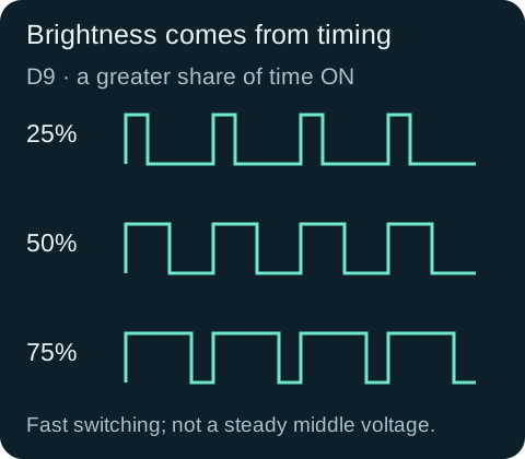
Digital pin 9 supports pulse-width modulation: it switches rapidly between low and high, with the brightness setting controlling the proportion of time on. A middle setting is not a steady 2.5-volt output. This switching method matters here because we are dimming a light. The shield’s LEDs on D9, D10 and D11 support it; D8, D12 and D13 do not provide the same fading behaviour.
setup() prepares the output and serial connection once. loop() keeps sampling so the light follows your hand. Separate reading and brightness variables keep the original measurement available for checking.
Read this part of the actual starter
void loop() {
  int reading = analogRead(potPin);
  int brightness = map(reading, 0, 1023, 0, 255);
  analogWrite(ledPin, brightness);
  Serial.print("knob:"); Serial.print(reading);
  Serial.print(",brightness:"); Serial.println(brightness);
  delay(25);
}
map(reading, 0, 1023, 0, 255) rescales an integer. analogWrite on PWM pin D9 sets duty cycle, not a steady analogue voltage. The output repeatedly switches between LOW and HIGH.
Work through one case
Reading 512 maps to 127 because integer arithmetic truncates. 0 gives off; 1023 gives 255, fully on. A perceived halfway brightness need not match halfway duty cycle.
Your turn: complete the trace
Reading 0 maps to 0; reading 1023 maps to ___; reading 512 maps to ___.
Compare your trace after trying
255 and 127 with integer map arithmetic.
If your answer differs
Name the units and valid range at each step.
Step 7 — Change one thing
Reverse the output range to 255, 0. Predict the result before uploading. Then try D10 instead of D9. Keep the original input range.
Run a controlled experiment
Reverse the dimmer so the lowest reading gives maximum duty cycle. Predict outputs at 0, 512 and 1023 before editing.
- Save a copy of the working starter. Reset the board so stored state begins from the declared values.
- Write the expected result before editing. Change only the named factor; keep wiring and other settings fixed.
- Edit the C++ in the editor, Verify, then Upload to the connected Uno. The starter simulation does not execute your edited C++.
- Repeat the same input sequence. Record input, expected output, observed output and an explanation. Use labelled serial values where the sketch provides them.
- If the result differs, inspect the relevant condition and pin before changing another factor. Restore and upload the saved starter to recover.
Core task: explain one changed case. Optional extension: choose a boundary or timing case and justify the extra test. Use a paper trace or annotated screenshot when physical manipulation is inaccessible; distinguish predictions from measurements.
Step 8 — Check your understanding
If the light only jumps between off and on, check that ledPin is 9, 10 or 11 and that the code uses analogWrite. Explain why sending 1023 directly is not a valid brightness setting.
If nothing changes: check the power light, successful upload and the selected Uno port. Disconnect power before reseating a shield. Read the first compiler error before changing several lines at once.
Independent check — try before revealing
A student sends raw reading 900 directly to analogWrite and expects a 90% command. What is wrong?
Hint
Name the units and valid range at each step.
Reasoning and feedback
The scales differ: raw input is 0–1023, but this PWM command must be 0–255. Map it first; 900 maps to 224, about 88% duty.
Use a PWM-capable pin. analogRead and analogWrite use different numerical ranges on this board.
If your explanation missed a condition or stored value, add that column to your trace and try a new input. A working upload alone does not answer this check.
Step 9 — From the moving wiper to brightness
The sketch reads potPin at A5 and maps reading from 0–1023 into brightness from 0–255.
Choose Cutaway and turn Wiper load off to represent the shield’s A5 input, which draws very little current. Move Turn the shaft to 25%, 50% and 75%. Record wiper voltage and ADC reading, and follow the moving contact on the resistive track.
Predict and explain: At half travel, why is the ADC reading about 512 but the PWM command about 127?
Check your explanation
The values describe different scales. The ADC encodes the measured input voltage; integer map() converts that reading into the 8-bit PWM duty command used by analogWrite(). With the illustrated 5 V reference and no wiper load, the three positions give about 1.25 V / 256, 2.50 V / 512 and 3.75 V / 767. A voltage is available at A5 even though almost no current enters that input.
Step 10 — Separate LED current from PWM duty
The knob changes the analogWrite(ledPin, brightness) command on D9. This red, two-lead LED exposes the same light-emitting principle used by the shield’s indicators; their colour and package can differ.
Choose Cutaway and find the tiny chip, reflector cup and bond wire. Leave Reverse polarity off, set Supply voltage to 5 V, then press Play blink. Watch current and light switch together. Pause before changing the supply to 3 V and then 1 V; the explorer keeps a 220 Ω resistor in series.
Predict and explain: Does a half-scale PWM command mean that the LED sees a steady half-voltage?
Check your explanation
No. D9 switches between HIGH and LOW. A half-scale command spends roughly half of each PWM cycle on. The LED’s on-state current is limited by the circuit; average light changes with the time spent on. The supply slider changes forward current during an on state. The lesson’s sketch separately determines which outputs are on and for how long.
