

Bounce between two lights
Use thresholds and memory to select an output without needing a perfect sensor reading.
Step 1 — What you will discover
Make a decision from an analogue reading and preserve the previous state between decision points.
Predict: After selecting D13 at one end, which LED stays on when you return to the middle?
Before you begin
Retrieve LOW/HIGH and Boolean true/false.
Your goal: Explain state that survives a loop. Show this with a prediction, a tested change and an explanation using the program’s names.
Retrieve one idea: what input, state or output did you change in the previous project?
Need a reminder? Turn the knob, dim the light.
Step 2 — Meet this circuit
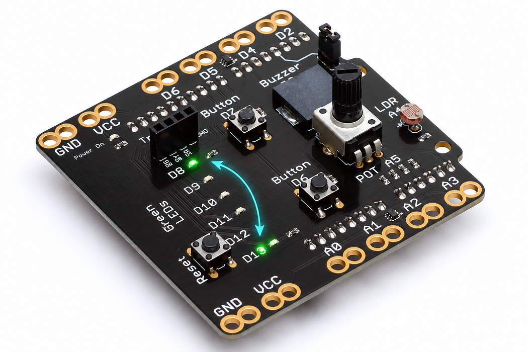
Use an Arduino Uno with the Crack the Code shield. The shield already connects its LEDs, knob, light sensor and buttons; this activity needs no jumper wires or breadboard.
If the shield is not fitted, disconnect USB power, align every shield pin with the Uno sockets, and press evenly without bending the pins. Reconnect the Uno with a USB data cable. Leave the traffic-light module disconnected for this activity.
Step 3 — Upload your program
Open the example below. Read the English plan, then choose Arduino C++ from the language selector and Arduino Uno from the board selector. Select Verify to compile. Select Pair board…, choose the Uno’s serial port, then select Upload. Use Chrome or Edge on a desktop computer with this HTTPS page for browser upload. If browser upload is unavailable, copy the complete C++ sketch into Arduino IDE, choose Arduino Uno and its port, and upload there.
Each upload replaces the previous program. Edit the supplied C++ when trying the challenges, then verify and upload again.
After upload, select Open Serial Monitor and set 9600 baud. Close other serial programs first so only one application owns the port. The Plot tab can display the labelled numeric readings.
Step 4 — Read, edit and run
The English plan and complete Arduino sketch describe the same program. Keep one working copy before making changes.
Step 5 — Run it and collect evidence
D8 is selected at startup. Turn to the high-reading end to select D13, then return to the middle. D13 should remain on. Reach the low-reading end and D8 takes over.
Step 6 — Explain what happened
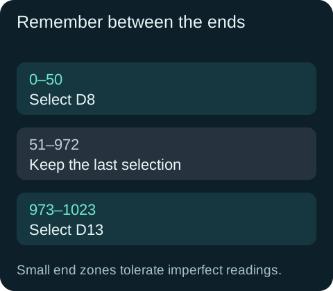
A real knob may not produce exactly 0 or 1023. Small end zones make the control reliable. The if and else if only change highSelected near an end. In the middle neither runs, so the variable remembers the previous choice.
The expressions after ? and : choose the output state: condition ? valueIfTrue : valueIfFalse. One LED is always the opposite of the other.
Read this part of the actual starter
void loop() {
  int reading = analogRead(potPin);
  if (reading <= 50) highSelected = false;
  else if (reading >= 973) highSelected = true;
  digitalWrite(lowLed, highSelected ? LOW : HIGH);
  digitalWrite(highLed, highSelected ? HIGH : LOW);
  Serial.print("knob:"); Serial.println(reading);
  delay(25);
}
Global highSelected survives from one pass through loop() to the next. At <=50 it becomes false; at >=973 it becomes true. Between those limits neither assignment runs. condition ? a : b selects one of two values.
Work through one case
Readings 20 → 600 → 990 → 600 produce false → false → true → true. The same middle reading can therefore produce two different outputs depending on history.
Your turn: complete the trace
Start highSelected=false. After readings 990, 700, 40, the remembered choices are true, ___, ___.
Compare your trace after trying
true, then false. 700 is between the thresholds, so it retains the prior true state.
If your answer differs
Look for which assignment actually executes in the middle range.
Step 7 — Change one thing
Change the thresholds to 300 and 700. Predict where the light changes, then test from both directions. Keep the low threshold smaller than the high threshold.
Run a controlled experiment
Change the two switching points to 200 and 800. Trace 100, 500, 900, 500 and explain why a single threshold would behave differently.
- Save a copy of the working starter. Reset the board so stored state begins from the declared values.
- Write the expected result before editing. Change only the named factor; keep wiring and other settings fixed.
- Edit the C++ in the editor, Verify, then Upload to the connected Uno. The starter simulation does not execute your edited C++.
- Repeat the same input sequence. Record input, expected output, observed output and an explanation. Use labelled serial values where the sketch provides them.
- If the result differs, inspect the relevant condition and pin before changing another factor. Restore and upload the saved starter to recover.
Core task: explain one changed case. Optional extension: choose a boundary or timing case and justify the extra test. Use a paper trace or annotated screenshot when physical manipulation is inaccessible; distinguish predictions from measurements.
Step 8 — Check your understanding
Why are ranges more dependable than testing equality with the exact end readings? If one end never selects, inspect the printed minimum and maximum and place the thresholds inside that range.
If nothing changes: check the power light, successful upload and the selected Uno port. Disconnect power before reseating a shield. Read the first compiler error before changing several lines at once.
Independent check — try before revealing
Why can a reading of 500 light either LED? What if highSelected were initialised inside loop?
Hint
Look for which assignment actually executes in the middle range.
Reasoning and feedback
At 500 neither threshold changes the stored choice, so history decides. Reinitialising inside loop resets it false on every pass and destroys that memory.
Putting bool highSelected = false inside the loop would erase its memory each pass.
If your explanation missed a condition or stored value, add that column to your trace and try a new input. A working upload alone does not answer this check.
Step 9 — The knob reports position, the code remembers
The bouncer selects D8 near the low end and D13 near the high end. highSelected keeps its previous value between the thresholds.
Choose Cutaway and turn Wiper load off to represent the shield’s A5 input, which draws very little current. Move Turn the shaft to 25%, 50% and 75%. Record wiper voltage and ADC reading, and follow the moving contact on the resistive track.
Predict and explain: Turn to 100%, then back to 50%. The wiper voltage has changed; must the selected LED change too?
Check your explanation
No. The analogue input reports the new position continuously, but the program changes highSelected only when reading is at most 50 or at least 973. A middle position leaves the previous selection intact. With the illustrated 5 V reference and no wiper load, the three positions give about 1.25 V / 256, 2.50 V / 512 and 3.75 V / 767. A voltage is available at A5 even though almost no current enters that input.
