

Measure changing light
Investigate the light sensor and collect a useful calibration range.
Step 1 — What you will discover
Use observations to calibrate a sensor instead of assuming every room produces the same numbers.
Predict: Will the value rise or fall when you cover the sensing face?
Before you begin
Read labelled serial values and keep test conditions repeatable.
Your goal: Calibrate a sensor before making decisions. Show this with a prediction, a tested change and an explanation using the program’s names.
Retrieve one idea: what input, state or output did you change in the previous project?
Need a reminder? Bounce between two lights.
Step 2 — Meet this circuit
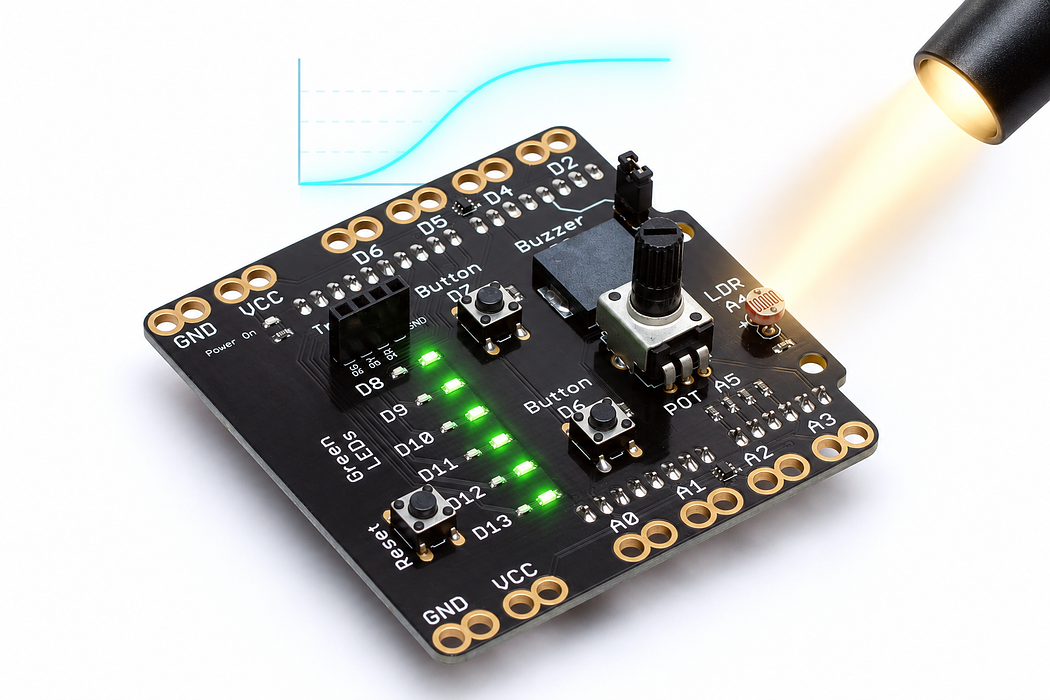
Use an Arduino Uno with the Crack the Code shield. The shield already connects its LEDs, knob, light sensor and buttons; this activity needs no jumper wires or breadboard.
If the shield is not fitted, disconnect USB power, align every shield pin with the Uno sockets, and press evenly without bending the pins. Reconnect the Uno with a USB data cable. Leave the traffic-light module disconnected for this activity.
Step 3 — Upload your program
Open the example below. Read the English plan, then choose Arduino C++ from the language selector and Arduino Uno from the board selector. Select Verify to compile. Select Pair board…, choose the Uno’s serial port, then select Upload. Use Chrome or Edge on a desktop computer with this HTTPS page for browser upload. If browser upload is unavailable, copy the complete C++ sketch into Arduino IDE, choose Arduino Uno and its port, and upload there.
Each upload replaces the previous program. Edit the supplied C++ when trying the challenges, then verify and upload again.
After upload, select Open Serial Monitor and set 9600 baud. Close other serial programs first so only one application owns the port. The Plot tab can display the labelled numeric readings.
Step 4 — Read, edit and run
The English plan and complete Arduino sketch describe the same program. Keep one working copy before making changes.
Step 5 — Run it and collect evidence
Read the small light-dependent resistor beside A4. Record values in room light, under your hand, and with a nearby lamp shining on it. Use ordinary room lighting; do not heat the sensor. Hold each condition steady for several readings.
Step 6 — Explain what happened
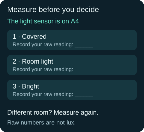
The light-dependent resistor changes resistance with illumination. The shield combines it with another resistor to make a changing voltage at A4. The Uno reads that voltage as a number. On this shield brighter light should give higher readings; verify your actual results before choosing thresholds.
These are raw readings, not lux or a percentage of sunlight. Sensor variation, shadows and room lighting change the range. Keep a covered reading and a bright reading for the next activity.
Read this part of the actual starter
void loop() {
  int reading = analogRead(lightPin);
  Serial.print("light:"); Serial.println(reading);
  delay(100);
}
lightPin identifies A4. Each loop takes one raw sample and prints it with a label. The sketch does not calculate lux. The LDR belongs to a voltage divider, so the direction of the change depends on its wiring.
Work through one case
Collect covered, room and brighter conditions three times each. If your covered reading is 780 and brighter is 180, increasing light decreases the reading on that circuit.
Your turn: complete the trace
Trial ranges are covered 760–790 and room 300–340. A separating threshold could be ___; darker means a ___ reading.
Compare your trace after trying
For example 550; larger. Any justified threshold between the two ranges can separate these observations.
If your answer differs
Compare measured ranges before choosing a threshold.
Step 7 — Change one thing
Move your hand closer without fully covering the sensor and plot the gradual change. Repeat with a different lamp direction. Describe a change that came from the environment rather than the program.
Run a controlled experiment
Choose a repeatable way to distinguish covered from uncovered. Use ranges from your measurements instead of copying a universal threshold.
- Save a copy of the working starter. Reset the board so stored state begins from the declared values.
- Write the expected result before editing. Change only the named factor; keep wiring and other settings fixed.
- Edit the C++ in the editor, Verify, then Upload to the connected Uno. The starter simulation does not execute your edited C++.
- Repeat the same input sequence. Record input, expected output, observed output and an explanation. Use labelled serial values where the sketch provides them.
- If the result differs, inspect the relevant condition and pin before changing another factor. Restore and upload the saved starter to recover.
Core task: explain one changed case. Optional extension: choose a boundary or timing case and justify the extra test. Use a paper trace or annotated screenshot when physical manipulation is inaccessible; distinguish predictions from measurements.
Step 8 — Check your understanding
If turning the knob changes the reading, check that the sketch uses A4. If the line is flat, remove anything blocking the sensing face and compare clearly different light levels.
If nothing changes: check the power light, successful upload and the selected Uno port. Disconnect power before reseating a shield. Read the first compiler error before changing several lines at once.
Independent check — try before revealing
Would that threshold automatically work on a reversed divider or in another room?
Hint
Compare measured ranges before choosing a threshold.
Reasoning and feedback
No. Re-measure both conditions and inspect the direction. Thresholds depend on wiring and environment; raw readings are not lux.
Do not assume brighter always means a larger number. Keep the lamp distance and sensor orientation controlled.
If your explanation missed a condition or stored value, add that column to your trace and try a new input. A working upload alone does not answer this check.
Step 9 — Look inside the light sensor
The light sensor supplies a changing input to analogRead(lightPin) at A4.
Open Cutaway, leave Power on, and compare Change the light at 25% and 75%. Record relative resistance and current. Find the two metal electrodes and the light-sensitive material between them; current crosses those gaps.
Predict and explain: Does the serpentine line act like one long wire, or does current cross the sensitive gaps between electrodes?
Check your explanation
The two electrode regions form many adjacent edges. Current crosses the photoconductive gaps between them, rather than following the gap as a metal wire. More light lowers the cell’s resistance. At the same applied voltage this allows more current. On the shield, the LDR forms a voltage divider read at A4; use your recorded dark and bright readings to establish the ADC direction and range. The percentages here describe relative illumination and current, not lux or the sketch’s calibrated light level.
