

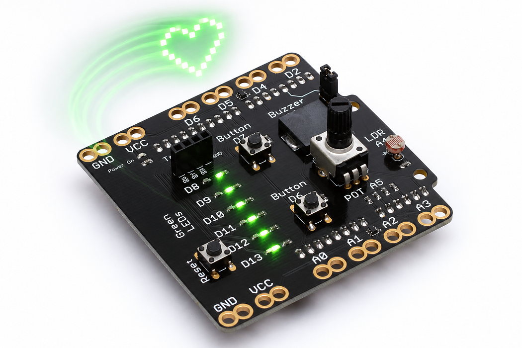
Paint a message with moving light
Turn six LEDs into the columns of a tiny persistence-of-vision sign and design your own pattern.
Step 1 — Predict what six lights can draw
Six LEDs can show a vertical line. If that line moves while its pattern changes, it can also paint a two-dimensional image. You will display a small “HI” message, then design a pattern of your own.
Predict what you will see while the shield is still. Why should sideways motion reveal something different?
Before you begin
Before running: six bit weights are 1,2,4,8,16,32. & tests overlapping set bits; 1 << row selects a weight. Decode one column while the board is still.
Your goal: Read bit masks as a spatial pattern. Show this with a prediction, a tested change and an explanation using the program’s names.
Retrieve one idea: what input, state or output did you change in the previous project?
Need a reminder? Hear and see the light level.
Step 2 — Read the rows and columns
The six LEDs are the six rows, D8 at the top through D13 at the bottom. Time supplies the columns from left to right. Here is the intended grid, with # meaning lit:
#...#.#####
#...#...#..
#####...#..
#...#...#..
#...#...#..
#...#.#####
A dot is an unlit position. The blank column between letters keeps them separate.
Step 3 — Program the shield
Choose Arduino Uno, then Verify and Upload the supplied sketch. The English instructions describe the same behaviour as the C++ beside them. Keep the USB cable connected while you test.
Step 4 — Find a comfortable sweep
Hold the assembled board securely by its edges, with slack in the USB cable. Hold D7 and make a small, smooth sideways sweep in a dim room. Keep the LEDs roughly vertical and do not swing the board by its cable.
At rest, flickering LEDs are expected. In motion, look for the two-letter pattern. The return sweep can look mirrored because this simple program does not measure movement direction. A phone photo with a longer exposure can help you inspect the pattern.
Step 5 — Explain the timing and the bits
Each array entry is one column. In a six-bit value, the weights from D8 to D13 are 1, 2, 4, 8, 16 and 32. A value of 63 lights every row; 4 lights only the third row; 33 lights the top and bottom rows.
Each column lasts 2200 microseconds, or 2.2 milliseconds. Use delayMicroseconds here rather than putting a fractional number into the millisecond delay function. The spacing you see also depends on how quickly you move the board.
Read this part of the actual starter
void showColumn(byte bits) {
  for (byte row = 0; row < 6; ++row) {
    digitalWrite(LED_PINS[row], (bits & (1 << row)) ? HIGH : LOW);
  }
}
void setup() {
  pinMode(BUTTON_PIN, INPUT);
  for (byte row = 0; row < 6; ++row) pinMode(LED_PINS[row], OUTPUT);
}
void loop() {
  if (digitalRead(BUTTON_PIN) == HIGH) {
    for (byte column = 0; column < COLUMN_COUNT; ++column) {
      if (digitalRead(BUTTON_PIN) != HIGH) break;
      showColumn(columns[column]);
1 << row selects one bit; bits & mask tests that bit. columns[] stores a sequence of six-bit LED patterns. One column is displayed for 2200 microseconds before the next. Movement spreads time across space.
Work through one case
33 is binary 100001, so only rows 0 and 5 light. 63 is 111111, all six. 4 is 000100, row 2 only. Column order affects the perceived letter.
Your turn: complete the trace
For bits=33, row 0 mask=1 gives a nonzero result; row 2 mask=4 gives ___; row 5 gives ___.
Compare your trace after trying
0, then 32. Rows 0 and 5 light.
If your answer differs
Write the bit weights and convert microseconds to milliseconds.
Step 6 — Draw and encode your own symbol
Draw a six-row pattern on squared paper. For each column, add the weights of its lit rows and enter that number into columns. The program calculates the number of columns automatically.
First change just one column of the H. Then try a three-column box using {63, 33, 63}. Predict its appearance before sweeping it.
Run a controlled experiment
Design one six-row symbol on squared paper, convert each column to a number and check it stationary before moving the board gently in a clear area.
- Save a copy of the working starter. Reset the board so stored state begins from the declared values.
- Write the expected result before editing. Change only the named factor; keep wiring and other settings fixed.
- Edit the C++ in the editor, Verify, then Upload to the connected Uno. The starter simulation does not execute your edited C++.
- Repeat the same input sequence. Record input, expected output, observed output and an explanation. Use labelled serial values where the sketch provides them.
- If the result differs, inspect the relevant condition and pin before changing another factor. Restore and upload the saved starter to recover.
Core task: explain one changed case. Optional extension: choose a boundary or timing case and justify the extra test. Use a paper trace or annotated screenshot when physical manipulation is inaccessible; distinguish predictions from measurements.
Step 7 — Check and improve the image
Compare COLUMN_US values of 1500, 2200 and 3500 while keeping your sweep similar. Which setting makes the image easiest to distinguish? Explain how changing time per column changes its apparent width.
- Nothing lights: hold D7 and check the upload.
- Only a bright streak: use a dimmer room and vary the sweep speed.
- Image is mirrored on the return: expected without a motion sensor; judge one sweep direction.
- Rows are wrong: bit zero is D8, not D13.
Independent check — try before revealing
Decode 18 into the lit rows. How long do 11 columns at 2200 microseconds each take, excluding the gap?
Hint
Write the bit weights and convert microseconds to milliseconds.
Reasoning and feedback
18=16+2, so rows 4 and 1. 11×2200=24200 microseconds=24.2 ms.
Microseconds and milliseconds differ by a factor of 1000. A static row of LEDs does not display the entire word at once.
If your explanation missed a condition or stored value, add that column to your trace and try a new input. A working upload alone does not answer this check.
Step 8 — A message made from separate flashes
Each bit in columns[] decides whether one of D8–D13 is HIGH for the current column. This red, two-lead LED exposes the same light-emitting principle used by the shield’s indicators; their colour and package can differ.
Choose Cutaway and find the tiny chip, reflector cup and bond wire. Leave Reverse polarity off, set Supply voltage to 5 V, then press Play blink. Watch current and light switch together. Pause before changing the supply to 3 V and then 1 V; the explorer keeps a 220 Ω resistor in series.
Predict and explain: Does one LED physically change shape to draw a letter?
Check your explanation
No. Each junction emits light at its own location. The timed columns and your movement place those flashes at different positions, producing the visible pattern. The explorer’s slow blink reveals the individual on/off events; the sketch uses much shorter column times. The supply slider changes forward current during an on state. The lesson’s sketch separately determines which outputs are on and for how long.
Step 9 — Why releasing the button ends the message
This sketch checks the D7 level before starting a column sequence and again before displaying each next column.
Choose Cutaway. Move Button travel from released to fully pressed, hold it there, then release it. Watch the spring dome meet and leave the contact. Compare the D7 state and voltage at each point; on this shield a pressed button reads HIGH.
Predict and explain: Does this program need to remember a toggle to stop on release?
Check your explanation
No. It directly checks whether the momentary input is still HIGH. Release opens the contact, the next check breaks out of the column loop, and showColumn(0) clears the lights. The switch is momentary: its contact opens on release. Any remembered output belongs to the program. The cutaway shows a clean contact transition; real switches may bounce, which is why some sketches debounce their input.
