

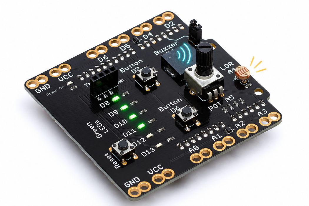
Hear and see the light level
Calibrate two light conditions, show the range on six LEDs and turn brightness into a beep rate.
Step 1 — Predict a meter you can hear
You will make a relative light meter with two outputs: more LEDs and faster beeps mean a brighter reading. The beep’s pitch stays the same.
Before programming, predict what covering the light sensor should do. You will also learn why a useful sensor scale starts with calibration rather than a magic pair of fixed numbers.
Before you begin
Know a state variable, array loop and elapsed time; long total holds the sum of 16 ADC samples before division.
Your goal: Coordinate calibration and timed outputs. Show this with a prediction, a tested change and an explanation using the program’s names.
Retrieve one idea: what input, state or output did you change in the previous project?
Need a reminder? Roll an electronic die.
Step 2 — Identify the sensing surface
Find the light-dependent resistor beside the A4 label. Leave its striped face clear of fingers, wires and the USB cable except when deliberately covering it. Use D7 to save calibration points, LEDs D8–D13 for the bar and the D3 buzzer for sound.
The potentiometer at A5 is not the sensor for this experiment.
Step 3 — Program the shield
Choose Arduino Uno, then Verify and Upload the supplied sketch. The English instructions describe the same behaviour as the C++ beside them. Keep the USB cable connected while you test.
Step 4 — Save a dark reading
Open the serial console at 9600 baud. While D8 flashes, cover the light sensor completely, then press and release D7 once. The console saves an averaged dark reading and asks for the bright condition.
Write down this number. It is an analog reading, not a light value in lux.
Step 5 — Save a bright reading
Uncover the sensor in the room’s normal light. While D13 flashes, press and release D7. Write down the second number. If the console reports too little contrast, increase the difference between covered and uncovered conditions and try again.
The program requires separated endpoints so the scale is meaningful. It also works if your module’s raw readings decrease as the light increases.
Step 6 — Run a controlled comparison
Move your hand gradually toward the sensing face without touching it. The bar should shrink and the time between beeps should increase. Uncover it: more LEDs and faster beeps should return.
Record three conditions: covered, partly shaded and uncovered. Compare the raw reading, relative percentage and number of lit LEDs. Conditions beyond your calibration endpoints are limited to 0 or 100 percent.
Step 7 — Explain calibration and two output scales
map converts the measured dark-to-bright range into a percentage. constrain keeps that result inside the chosen display range. A second mapping chooses the LED count; a third chooses the beep interval.
The program uses a fixed 650-hertz note lasting 35 milliseconds. Brightness changes its repetition rate, not its pitch. No calibrated lux measurement is implied by a percentage of your two reference conditions.
Read this part of the actual starter
void loop() {
  const unsigned long now = millis();
  const bool pressed = newPress(now);
  if (stage < 2) {
    showBar(0);
    digitalWrite(LED_PINS[stage == 0 ? 0 : 5], (now / 250) % 2 ? HIGH : LOW);
    if (!pressed) return;
    if (stage == 0) {
      darkReading = averagedLight();
      stage = 1;
      Serial.print(F("Dark:")); Serial.println(darkReading);
      Serial.println(F("Uncover in room light, then press D7 to save bright."));
    } else {
      brightReading = averagedLight();
stage controls dark capture, bright capture and measuring. averagedLight totals 16 samples in a long before dividing; showBar lights all indices below count. Separate timestamps schedule sampling, sound and reporting.
Work through one case
Relative light 50 maps to three LEDs and a beep interval of 510 ms. The pitch stays 650 Hz; brightness changes the gap between beeps, not pitch.
Your turn: complete the trace
With calibrated light=50%, the bar count is ___ and the beep interval is ___ ms.
Compare your trace after trying
3 LEDs and 510 ms. map(50,0,100,900,120) gives 510.
If your answer differs
Distinguish reducing random variation from establishing a useful measurement range.
Step 8 — Change the feedback, then check it
Change the interval limits from 900 and 120 to 1600 and 200. Predict which condition gets the longest silence before uploading. Reset and calibrate again after moving to a different room.
Explain why hard-coded readings copied from somebody else’s room can make a poor meter.
- D8 or D13 keeps flashing: the program is waiting for a calibration press on D7.
- The bar stays full or empty: recalibrate and make sure nothing blocks the sensor unintentionally.
- Too little contrast: check A4, cover the sensing face more fully, and change the bright condition.
- Bar works but beeps do not: check the buzzer jumper.
Run a controlled experiment
Record calibration values and test 0%, near 50%, and 100%. Change only the beep-rate mapping and explain which outputs should remain unchanged.
- Save a copy of the working starter. Reset the board so stored state begins from the declared values.
- Write the expected result before editing. Change only the named factor; keep wiring and other settings fixed.
- Edit the C++ in the editor, Verify, then Upload to the connected Uno. The starter simulation does not execute your edited C++.
- Repeat the same input sequence. Record input, expected output, observed output and an explanation. Use labelled serial values where the sketch provides them.
- If the result differs, inspect the relevant condition and pin before changing another factor. Restore and upload the saved starter to recover.
Core task: explain one changed case. Optional extension: choose a boundary or timing case and justify the extra test. Use a paper trace or annotated screenshot when physical manipulation is inaccessible; distinguish predictions from measurements.
Independent check — try before revealing
If dark=400 and bright=410, why does measurement not begin? Would averaging alone fix this?
Hint
Distinguish reducing random variation from establishing a useful measurement range.
Reasoning and feedback
The contrast is only 10 counts, below the required 30. Change the lighting and recapture; averaging does not create missing calibration contrast.
Averaging reduces some variation but does not calibrate the sensor. The code rejects endpoints separated by fewer than 30 ADC counts.
If your explanation missed a condition or stored value, add that column to your trace and try a new input. A working upload alone does not answer this check.
Step 9 — Follow the physical measurement before calibration
A4 supplies the raw readings used by averagedLight(). Button presses save darkReading and brightReading.
Open Cutaway, leave Power on, and compare Change the light at 25% and 75%. Record relative resistance and current. Find the two metal electrodes and the light-sensitive material between them; current crosses those gaps.
Predict and explain: Does pressing the calibration button alter the LDR’s sensitive material?
Check your explanation
No. Calibration stores reference measurements in the program. The same photoconductive material continues responding to light, while map() expresses its readings on the chosen relative scale. More light lowers the cell’s resistance. At the same applied voltage this allows more current. On the shield, the LDR forms a voltage divider read at A4; use your recorded dark and bright readings to establish the ADC direction and range. The percentages here describe relative illumination and current, not lux or the sketch’s calibrated light level.
Step 10 — Pitch and beep spacing are different controls
This meter calls tone(BUZZER_PIN, 650, 35). Its changing interval determines when each short beep starts.
Choose Cutaway and press Play animation. Compare 440 Hz and 880 Hz using Change the pitch; use Tone off to enable the optional sound. The visible bending is slowed and enlarged. Pause, then drag Inspect one cycle through rising, steady and falling voltage.
Predict and explain: As the measured light increases, does this sketch raise the pitch of each beep or reduce the time between beeps?
Check your explanation
It reduces the interval from 900 toward 120 ms while keeping each beep at 650 Hz for 35 ms. Set the explorer to 650 Hz to inspect that sounder; its pitch slider is a separate experiment, not the meter’s light-to-interval mapping. Changing voltage bends the bonded ceramic and brass diaphragm. Charge moves onto and off the electrodes, reversing during discharge; it does not pass through the ceramic. Try Electron flow to see the opposite direction convention for the same electrical behaviour.
Step 11 — How the light bar communicates a measurement
The sketch maps relative light into count and calls showBar(count) to light that many indicators. This red, two-lead LED exposes the same light-emitting principle used by the shield’s indicators; their colour and package can differ.
Choose Cutaway and find the tiny chip, reflector cup and bond wire. Leave Reverse polarity off, set Supply voltage to 5 V, then press Play blink. Watch current and light switch together. Pause before changing the supply to 3 V and then 1 V; the explorer keeps a 220 Ω resistor in series.
Predict and explain: When the bar gets longer, must each already-lit LED become brighter?
Check your explanation
No. showBar chooses how many outputs are HIGH. It does not apply PWM brightness commands to each LED, so the length of the bar carries the measurement. The supply slider changes forward current during an on state. The lesson’s sketch separately determines which outputs are on and for how long.
