

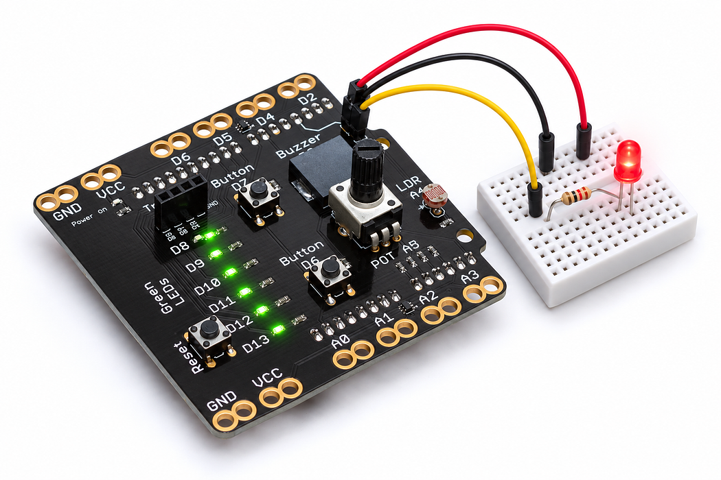
Connect and blink an external LED
Build a simple output circuit with one LED, a series resistor and three individual connections.
Step 1 — Predict the complete circuit
You will move beyond the onboard lights and control one separate LED. Gather a standard indicator LED, a 220-ohm resistor and three insulated clip leads. Keep this circuit disconnected from USB while making or changing connections.
The path will be D5 → resistor → LED → ground. Predict why leaving either end disconnected stops the LED working.
Before you begin
Retrieve blink timing and the complete current path. Check polarity and a series resistor before power.
Your goal: Relate physical current paths to code. Show this with a prediction, a tested change and an explanation using the program’s names.
Retrieve one idea: what input, state or output did you change in the previous project?
Need a reminder? Paint a message with moving light.
Step 2 — Identify the LED and resistor
The LED has a direction: its longer leg is usually the anode; the shorter leg and flat edge identify the cathode. If its leads have already been trimmed, use the flat edge and the part’s markings rather than guessing from length.
The resistor limits current and has no polarity. A 220-ohm four-band resistor is red, red, brown, followed by its tolerance band. Keep the two LED legs apart and leave space between exposed clip jaws.
Step 3 — Connect the resistor to D5
Use a green or yellow clip lead to connect the shield’s D5 edge pad to one resistor leg. This is a switched output, so use a signal colour rather than red. The resistor can face either direction.
Step 4 — Connect the resistor to the anode
Use a second signal-coloured lead to connect the free resistor leg to the LED’s anode. The resistor and LED are now in series: current must pass through both.
Step 5 — Connect the cathode to ground
Use a black lead to connect the LED’s cathode to a shield ground pad. Check that no bare clip touches another clip, an adjacent pad or the other LED leg.
Follow the full path once with your finger before reconnecting USB. This build does not need a separate connection to the 5-volt pad; D5 supplies the controlled output.
Step 6 — Program the shield
Choose Arduino Uno, then Verify and Upload the supplied sketch. The English instructions describe the same behaviour as the C++ beside them. Keep the USB cable connected while you test.
Step 7 — Run and explain the blink
The external LED should spend half a second on and half a second off. D5 switches between high and low; the resistor limits current during the on time, and ground completes the return path.
One complete cycle lasts a second. Explain why the LED would remain off if its direction were reversed, even though the program kept running.
Step 8 — Change the pattern and check the circuit
Set ON_MS to 100 and OFF_MS to 900. Predict the cycle length and how the flash will look before uploading. Then restore the original values.
- No light: disconnect USB and check polarity, the D5 pad, and every clip’s metal-to-metal contact.
- Always on: check that the signal wire is on D5 rather than VCC.
- Intermittent flicker: secure loose clips and keep their exposed jaws separated.
- Never remove the resistor as a brightness experiment; change the timing instead.
Completion check: identify the anode, cathode, current-limiting resistor and ground return in your own circuit.
Read this part of the actual starter
void loop() {
  digitalWrite(LED_PIN, HIGH);
  delay(ON_MS);
  digitalWrite(LED_PIN, LOW);
  delay(OFF_MS);
}
LED_PIN is D5 for the external LED, not the shield LED D13. The program sets a known LOW state then alternates 500 ms on and off. Wiring still determines whether current can pass through the LED.
Work through one case
500 + 500 ms gives a one-second period. A correct sketch cannot fix a reversed LED or a missing series current-limiting resistor.
Your turn: complete the trace
At ON_MS=500 and OFF_MS=500, period=___ ms and frequency=___ Hz.
Compare your trace after trying
1000 ms and 1 Hz.
If your answer differs
Separate a successful upload from a complete conducting circuit.
Run a controlled experiment
With power disconnected, trace the complete path through pin, resistor, LED and ground. Diagnose a deliberately described reversed LED without removing the resistor.
- Save a copy of the working starter. Reset the board so stored state begins from the declared values.
- Write the expected result before editing. Change only the named factor; keep wiring and other settings fixed.
- Edit the C++ in the editor, Verify, then Upload to the connected Uno. The starter simulation does not execute your edited C++.
- Repeat the same input sequence. Record input, expected output, observed output and an explanation. Use labelled serial values where the sketch provides them.
- If the result differs, inspect the relevant condition and pin before changing another factor. Restore and upload the saved starter to recover.
Core task: explain one changed case. Optional extension: choose a boundary or timing case and justify the extra test. Use a paper trace or annotated screenshot when physical manipulation is inaccessible; distinguish predictions from measurements.
Independent check — try before revealing
The code uploads but the LED is dark. Give a safe diagnostic order without bypassing the resistor.
Hint
Separate a successful upload from a complete conducting circuit.
Reasoning and feedback
Disconnect power, check D5 and ground connections, breadboard rows, resistor continuity/path and LED polarity. Reconnect only after inspection; then confirm the selected board and latest upload.
An LED needs correct polarity and current limiting. Rewire only with power disconnected; inspect before reconnecting.
If your explanation missed a condition or stored value, add that column to your trace and try a new input. A working upload alone does not answer this check.
Step 9 — Look inside the LED
Switch to Cutaway and find the chip, reflector cup and fine bond wire. The flat rim and shorter lead mark the cathode. The explorer includes the same 220 Ω series resistor as your circuit.
Predict: will reducing the supply from 5 V to 1 V halve the light? Test 5 V, 3 V and 1 V, comparing current in milliamps with light output. Then try Reverse polarity in the explorer. Restore forward polarity and press Play blink to connect the internal view with the on/off pattern of your sketch.
Check your explanation
The LED does not behave like an ordinary resistor. Forward current rises sharply once the junction conducts; the series resistor limits that current. Electrons and holes recombine in the chip, releasing light. Reversing the supply blocks almost all current, so the LED stays dark. Conventional current and electron flow use opposite directions to describe the same electrical behaviour.
