

Show your working: circuits that build themselves, and a semester of VCE Systems Engineering
Hello and welcome to a big one. Two things went up on the site today, and they're the same idea pointed in two directions: show someone how a thing gets built, instead of handing them the finished article and wishing them luck.
Wiring diagrams that build themselves
A wiring diagram has always had the same flaw. It shows you the end state. Every wire is already in, every leg is already seated, and whoever's looking at it has to work backwards to guess the order somebody assembled it in. Most beginners start at the top left and hope.
So our circuits now record their own assembly. Each one carries an ordered series of snapshots with a caption on every move, and the diagram plays them back in order, animating each new wire on as it goes.
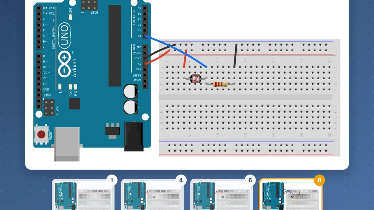
Here's PRP 3 from the new unit, light sensing with an LDR, in eight steps.
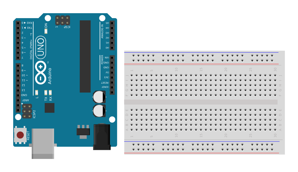
Step 1. The Uno's turned 180 degrees so its POWER and ANALOG IN headers face the breadboard. Every wire from here is a short hop across the gap instead of a long run around the outside.
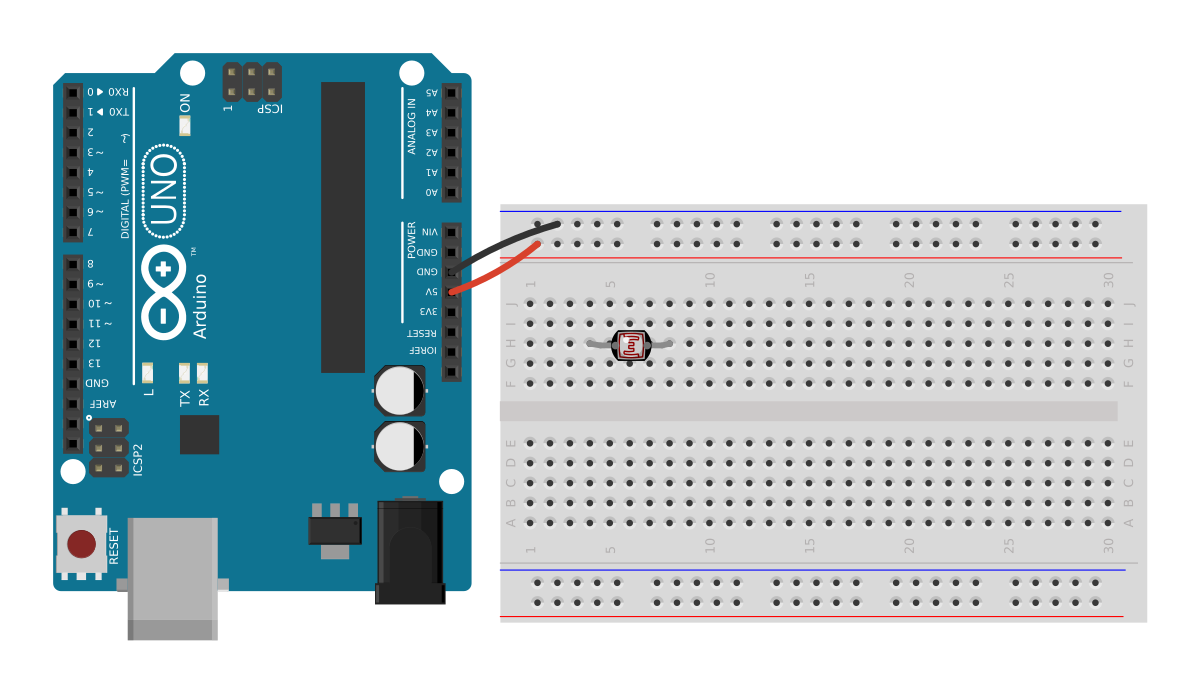
Step 4. Rails are live, and the LDR goes in across columns 4 and 8. Both legs at once, because it's one part, so it's one move.
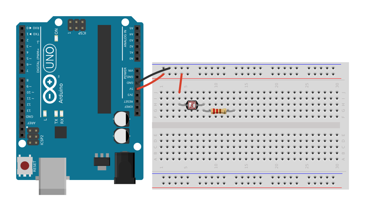
Step 6. The 10 kΩ resistor's left leg shares column 8 with the LDR's right leg, so those two are joined inside the board. That shared column is the measurement node.
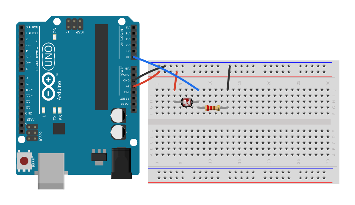
Step 8. Last wire: column 8 across to A0. The Uno now reads a voltage that rises and falls with the light on the LDR.
Parts go in the holes now, too. A resistor used to draw as a body floating above the board with a jumper running out to it, which is nobody's actual build. Legs get bent to reach their hole, the way you'd bend them at the bench.
While we were in there we found a good one. Every rail jumper had been landing about a hole and a half from where it's drawn, because a breadboard's power rails and its terminal rows don't share the same transform in the part artwork. Component legs looked perfect; rail jumpers sat in the gap between two sockets. It survived that long because the obvious check confirms it. Compare a wire's position against the part's connector list and you get a perfect match, however wrong the position is.
A whole semester of VCE Systems Engineering, free
Victoria's VCE Systems Engineering study design was reaccredited from 2026. Every teacher in the state is rebuilding the subject this year with nobody's materials from last year to work from, so Unit 1 is now up, free, no sign-in. The outcomes it maps to are there too, including the eight School-assessed Task criteria, so a Units 3 and 4 sequence can point at where each one gets taught.
It's a full semester. Ten sequences across 18 weeks, seven practical activities, five sample sketches, 32 glossary terms and a bill of materials you can hand to your business manager or add straight to a cart.
Both Areas of Study sit in the one unit, because they're one project. AoS1 designs an electrotechnological system, AoS2 produces it. Splitting them cuts the design process in half.
The order is deliberate. Sequences 1 to 5 teach the skills and run the practicals; 6 to 10 are the student's own design project. By the time a student writes a design brief, they already know what a sensor can and can't do, which heads off the usual failure of this unit: an ambitious brief the components can't deliver.
The practicals build on each other rather than sitting side by side.
- Voltage divider. Two resistors across the 5V rail. Calculate the junction voltage, then measure it.
- Current limiting an LED. The resistor is what makes it a circuit. Without one the LED draws all it can and destroys itself.
- Light sensing with an LDR. The same divider, with one leg that changes.
- Temperature and humidity with a DHT22. The sensor does its own conversion and hands the board real units.
- A threshold decision. Read a sensor, pick a number, drive an output.
- Hysteresis. Students meet it by hitting the chattering fault first, then fixing it.
- Automatic watering. Soil moisture in, pump out, through a motor driver, with the pump on its own supply sharing only a ground.
That last one carries a maximum pump run time, because a control system that can't fail safely isn't finished.

PRP 5 and PRP 6 run on exactly this hardware. Only the code changes, which is the whole point: hysteresis is a software fix for a fault students can watch happen. Thirteen steps.
There are three ways into the same content. The teacher dashboard has prep, safety, differentiation, the misconceptions students actually arrive with, and what counts as evidence. The student view has the activity and the code without the marking guide. And there are slide decks built for the projector, student-visible up front with speaker notes behind.
The per-student kit runs to an Uno R3 at $19.55 with the USB cable in the box, a full-size breadboard, jumpers, a resistor kit, LEDs, a couple of LDRs, a DHT22 and a soil moisture sensor. Multimeters, motor drivers and pumps are on the shared list, roughly one between four.
Take any circuit as a picture
Every circuit on the site is now also an image. Put .png or .svg on the end of its address:
https://littlebirdelectronics.com.au/circuits/Wo-VQ49_xxE.png?width=1200
Add ?step=4 and you get that frame of the build instead of the finished thing. That's how every picture in this post was made.
Take them for a worksheet, a slide, a lab report, an exam paper, whatever you're making. The real .fz is a click away as well, so you can open the sketch in desktop Fritzing and change it, or open it in the browser editor and draw your own from the 1,845-part catalogue.
Have a go
If you teach VCE Systems Engineering, the unit's there to be pulled apart. Take the practicals and drop your own project on the end, or take the project sequences and run them against gear you already own. Nothing's locked.
And if you build one of the seven circuits, we'd love to see it. Change a value, swap the sensor, break it and fix it again, and show us what you made.
