

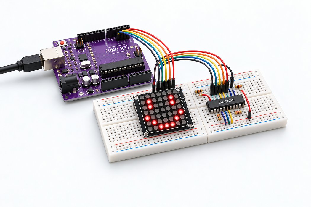
Draw patterns on the 8 × 8 matrix
Drive a row-anode, column-cathode 8×8 matrix with a MAX7219 in no-decode mode. Alternate a smile pattern and a diagonal.
Drive a row-anode, column-cathode 8×8 matrix with a MAX7219 in no-decode mode. Alternate a smile pattern and a diagonal.
Use the Uno R3 Learning Kit. Build with power disconnected, check the labelled connections, then upload the supplied sketch. Drag or zoom the 3D model to inspect it from any angle.
Identify your part
No matrix part number is specified in the kit listing. Verify the targeted row-anode, column-cathode pin map before following this build. A MAX7219 is required in addition to the matrix.
Also needed
Use an additional 830-contact breadboard and the kit’s mini breadboard. The matrix bridges their edges so neither row of jumper connections is hidden beneath its case.
Step 1 — Watch the complete build
Press Play for the narrated build. You can rotate and zoom the model while it plays, or follow the individual steps below.
Loading assembly…
Keep U S B disconnected while you build. On this breadboard, each group of five holes shares a connection; the centre channel separates the two halves. You can drag the 3D view to look around. Start with the supply. Connect the Arduino’s five volt output to the positive rail. That rail will power the display driver. Now connect Arduino ground to the ground rail. The driver and Arduino need this shared reference. The MAX7219 handles the fast scanning for us. Seat it across the centre channel, with its pin-one notch at the left. Add the mini breadboard beside the main board. The matrix will bridge the gap, leaving its connections accessible on both sides. This build uses the row-anode, column-cathode pin map listed below. Check your matrix against that map first, then seat it in the highlighted holes. Its display face stays clear of the wiring. Add the one hundred kilohm resistor here. It sets a low starting L E D current through the driver’s ISET pin. A resistor works in either direction. This one hundred nanofarad capacitor helps keep the driver’s supply steady during switching. It spans the positive and ground rails and has no polarity. The ten microfarad capacitor adds a little more supply buffering. Its positive lead goes to the positive rail; the stripe marks the negative lead, which goes to ground. Connect the driver’s power pin to the positive rail. This is its five volt supply. Connect the first ground pin on the driver to the ground rail. There’s a second ground pin on this driver. Connect that to the same ground rail too. Connect ISET to one end of the current-setting resistor. This is how the driver sets the L E D current. Connect the other end of that resistor to the positive rail. Connect digital pin eleven to the driver’s data input. This is the Uno’s controller data output pin; our program uses S P I to send the pattern data. Connect digital pin thirteen to the clock input. This is the S P I clock, which tells the driver when to read each bit. Digital pin ten connects to LOAD. The program pulses it to finish each command. That completes the three control signals. Now connect the driver’s segment D P output to the first anode row of the matrix. These segment outputs supply the rows, while the digit outputs will select the columns. Connect segment A on the driver to row 2 of the matrix. Connect segment B on the driver to row 3 of the matrix. Connect segment C on the driver to row 4 of the matrix. Connect segment D on the driver to row 5 of the matrix. Connect segment E on the driver to row 6 of the matrix. Connect segment F on the driver to row 7 of the matrix. Connect segment G to the eighth anode row. That finishes the row connections; next are the column returns. Connect digit zero on the driver to the first cathode column. These are switched returns, not ground wires: the driver selects each column in turn. Connect digit 1 on the driver to column 2 of the matrix. Connect digit 2 on the driver to column 3 of the matrix. Connect digit 3 on the driver to column 4 of the matrix. Connect digit 4 on the driver to column 5 of the matrix. Connect digit 5 on the driver to column 6 of the matrix. Connect digit 6 on the driver to column 7 of the matrix. Connect digit seven to the eighth column. With all the rows and columns connected, the driver can scan the whole matrix. Check all wiring. Connect the square U S B-B plug to the Uno and the U S B-A plug to your computer. Use Verify and Upload in the code editor below.
Step 2 — Understand the breadboard
Keep USB disconnected while you build. On this breadboard, each group of five holes shares a connection; the centre channel separates the two halves. You can drag the 3D view to look around.
Loading assembly…
Keep U S B disconnected while you build. On this breadboard, each group of five holes shares a connection; the centre channel separates the two halves. You can drag the 3D view to look around.
Step 3 — Connect Uno 5V → T+ rail 15
Start with the supply. Connect the Arduino’s five volt output to the positive rail. That rail will power the display driver.
| Connect | To |
|---|---|
| Uno 5V | T+ rail 15 |
Loading assembly…
Start with the supply. Connect the Arduino’s five volt output to the positive rail. That rail will power the display driver.
Step 4 — Connect Uno GND → T− rail 11
Now connect Arduino ground to the ground rail. The driver and Arduino need this shared reference.
| Connect | To |
|---|---|
| Uno GND | T− rail 11 |
Loading assembly…
Now connect Arduino ground to the ground rail. The driver and Arduino need this shared reference.
Step 5 — Place MAX7219 LED display driver
The MAX7219 handles the fast scanning for us. Seat it across the centre channel, with its pin-one notch at the left.
Exact breadboard holes
- driver · 1 · DIN → E14
- driver · 2 · DIG0 → E15
- driver · 3 · DIG4 → E16
- driver · 4 · GND → E17
- driver · 5 · DIG6 → E18
- driver · 6 · DIG2 → E19
- driver · 7 · DIG3 → E20
- driver · 8 · DIG7 → E21
- driver · 9 · GND → E22
- driver · 10 · DIG5 → E23
- driver · 11 · DIG1 → E24
- driver · 12 · LOAD → E25
- driver · 13 · CLK → F25
- driver · 14 · SEG A → F24
- driver · 15 · SEG F → F23
- driver · 16 · SEG B → F22
- driver · 17 · SEG G → F21
- driver · 18 · ISET → F20
- driver · 19 · VCC → F19
- driver · 20 · SEG C → F18
- driver · 21 · SEG E → F17
- driver · 22 · SEG DP → F16
- driver · 23 · SEG D → F15
- driver · 24 · DOUT → F14
Loading assembly…
The MAX7219 handles the fast scanning for us. Seat it across the centre channel, with its pin-one notch at the left.
Step 6 — Place Mini breadboard · 170 contacts
Add the mini breadboard beside the main board. The matrix will bridge the gap, leaving its connections accessible on both sides.
Loading assembly…
Add the mini breadboard beside the main board. The matrix will bridge the gap, leaving its connections accessible on both sides.
Step 7 — Place 8 × 8 LED matrix · 16 pins
This build uses the row-anode, column-cathode pin map listed below. Check your matrix against that map first, then seat it in the highlighted holes. Its display face stays clear of the wiring.
Exact breadboard holes
- display · 1 → Extension A4
- display · 2 → Extension A5
- display · 3 → Extension A6
- display · 4 → Extension A7
- display · 5 → Extension A8
- display · 6 → Extension A9
- display · 7 → Extension A10
- display · 8 → Extension A11
- display · 9 → J47
- display · 10 → J46
- display · 11 → J45
- display · 12 → J44
- display · 13 → J43
- display · 14 → J42
- display · 15 → J41
- display · 16 → J40
Loading assembly…
This build uses the row-anode, column-cathode pin map listed below. Check your matrix against that map first, then seat it in the highlighted holes. Its display face stays clear of the wiring.
Step 8 — Place 100 kΩ resistor
Add the one hundred kilohm resistor here. It sets a low starting LED current through the driver’s ISET pin. A resistor works in either direction.
Exact breadboard holes
- iset · Pin 0 → A27
- iset · Pin 1 → A31
Loading assembly…
Add the one hundred kilohm resistor here. It sets a low starting L E D current through the driver’s ISET pin. A resistor works in either direction.
Step 9 — Place 100 nF ceramic capacitor
This one hundred nanofarad capacitor helps keep the driver’s supply steady during switching. It spans the positive and ground rails and has no polarity.
Exact breadboard holes
- bypass · 0 → T+ rail 20
- bypass · 1 → T− rail 20
Loading assembly…
This one hundred nanofarad capacitor helps keep the driver’s supply steady during switching. It spans the positive and ground rails and has no polarity.
Step 10 — Place 10 µF electrolytic capacitor · 50 V
The ten microfarad capacitor adds a little more supply buffering. Its positive lead goes to the positive rail; the stripe marks the negative lead, which goes to ground.
Exact breadboard holes
- bulk · - → T− rail 24
- bulk · + → T+ rail 24
Loading assembly…
The ten microfarad capacitor adds a little more supply buffering. Its positive lead goes to the positive rail; the stripe marks the negative lead, which goes to ground.
Step 11 — Connect J19 → T+ rail 14
Connect the driver’s VCC pin to the positive rail. This is its five volt supply.
| Connect | To |
|---|---|
| J19 | T+ rail 14 |
Loading assembly…
Connect the driver’s power pin to the positive rail. This is its five volt supply.
Step 12 — Connect A17 → T− rail 13
Connect the first ground pin on the driver to the ground rail.
| Connect | To |
|---|---|
| A17 | T− rail 13 |
Loading assembly…
Connect the first ground pin on the driver to the ground rail.
Step 13 — Connect A22 → T− rail 17
There’s a second ground pin on this driver. Connect that to the same ground rail too.
| Connect | To |
|---|---|
| A22 | T− rail 17 |
Loading assembly…
There’s a second ground pin on this driver. Connect that to the same ground rail too.
Step 14 — Connect J20 → B27
Connect ISET to one end of the current-setting resistor. This is how the driver sets the LED current.
| Connect | To |
|---|---|
| J20 | B27 |
Loading assembly…
Connect ISET to one end of the current-setting resistor. This is how the driver sets the L E D current.
Step 15 — Connect B31 → T+ rail 26
Connect the other end of that resistor to the positive rail.
| Connect | To |
|---|---|
| B31 | T+ rail 26 |
Loading assembly…
Connect the other end of that resistor to the positive rail.
Step 16 — Connect Uno D11 PWM/MOSI → A14
Connect digital pin eleven to the driver’s data input. This is the Uno’s MOSI pin; our program uses SPI to send the pattern data.
| Connect | To |
|---|---|
| Uno D11 PWM/MOSI | A14 |
Loading assembly…
Connect digital pin eleven to the driver’s data input. This is the Uno’s controller data output pin; our program uses S P I to send the pattern data.
Step 17 — Connect Uno D13/SCK → J25
Connect digital pin thirteen to the clock input. This is the SPI clock, which tells the driver when to read each bit.
| Connect | To |
|---|---|
| Uno D13/SCK | J25 |
Loading assembly…
Connect digital pin thirteen to the clock input. This is the S P I clock, which tells the driver when to read each bit.
Step 18 — Connect Uno D10 PWM/SS → A25
Digital pin ten connects to LOAD. The program pulses it to finish each command. That completes the three control signals.
| Connect | To |
|---|---|
| Uno D10 PWM/SS | A25 |
Loading assembly…
Digital pin ten connects to LOAD. The program pulses it to finish each command. That completes the three control signals.
Step 19 — Connect J16 → H47
Now connect the driver’s segment D P output to the first anode row of the matrix. These segment outputs supply the rows, while the digit outputs will select the columns.
| Connect | To |
|---|---|
| J16 | H47 |
Loading assembly…
Now connect the driver’s segment D P output to the first anode row of the matrix. These segment outputs supply the rows, while the digit outputs will select the columns.
Step 20 — Connect J24 → H42
Connect segment A on the driver to row 2 of the matrix.
| Connect | To |
|---|---|
| J24 | H42 |
Loading assembly…
Connect segment A on the driver to row 2 of the matrix.
Step 21 — Connect J22 → Extension C11
Connect segment B on the driver to row 3 of the matrix.
| Connect | To |
|---|---|
| J22 | Extension C11 |
Loading assembly…
Connect segment B on the driver to row 3 of the matrix.
Step 22 — Connect J18 → H44
Connect segment C on the driver to row 4 of the matrix.
| Connect | To |
|---|---|
| J18 | H44 |
Loading assembly…
Connect segment C on the driver to row 4 of the matrix.
Step 23 — Connect J15 → Extension C4
Connect segment D on the driver to row 5 of the matrix.
| Connect | To |
|---|---|
| J15 | Extension C4 |
Loading assembly…
Connect segment D on the driver to row 5 of the matrix.
Step 24 — Connect J17 → Extension C10
Connect segment E on the driver to row 6 of the matrix.
| Connect | To |
|---|---|
| J17 | Extension C10 |
Loading assembly…
Connect segment E on the driver to row 6 of the matrix.
Step 25 — Connect J23 → Extension C5
Connect segment F on the driver to row 7 of the matrix.
| Connect | To |
|---|---|
| J23 | Extension C5 |
Loading assembly…
Connect segment F on the driver to row 7 of the matrix.
Step 26 — Connect J21 → Extension C8
Connect segment G to the eighth anode row. That finishes the row connections; next are the column returns.
| Connect | To |
|---|---|
| J21 | Extension C8 |
Loading assembly…
Connect segment G to the eighth anode row. That finishes the row connections; next are the column returns.
Step 27 — Connect A15 → H43
Connect digit zero on the driver to the first cathode column. These are switched returns, not ground wires: the driver selects each column in turn.
| Connect | To |
|---|---|
| A15 | H43 |
Loading assembly…
Connect digit zero on the driver to the first cathode column. These are switched returns, not ground wires: the driver selects each column in turn.
Step 28 — Connect A24 → Extension C6
Connect digit 1 on the driver to column 2 of the matrix.
| Connect | To |
|---|---|
| A24 | Extension C6 |
Loading assembly…
Connect digit 1 on the driver to column 2 of the matrix.
Step 29 — Connect A19 → Extension C7
Connect digit 2 on the driver to column 3 of the matrix.
| Connect | To |
|---|---|
| A19 | Extension C7 |
Loading assembly…
Connect digit 2 on the driver to column 3 of the matrix.
Step 30 — Connect A20 → H46
Connect digit 3 on the driver to column 4 of the matrix.
| Connect | To |
|---|---|
| A20 | H46 |
Loading assembly…
Connect digit 3 on the driver to column 4 of the matrix.
Step 31 — Connect A16 → Extension C9
Connect digit 4 on the driver to column 5 of the matrix.
| Connect | To |
|---|---|
| A16 | Extension C9 |
Loading assembly…
Connect digit 4 on the driver to column 5 of the matrix.
Step 32 — Connect A23 → H45
Connect digit 5 on the driver to column 6 of the matrix.
| Connect | To |
|---|---|
| A23 | H45 |
Loading assembly…
Connect digit 5 on the driver to column 6 of the matrix.
Step 33 — Connect A18 → H41
Connect digit 6 on the driver to column 7 of the matrix.
| Connect | To |
|---|---|
| A18 | H41 |
Loading assembly…
Connect digit 6 on the driver to column 7 of the matrix.
Step 34 — Connect A21 → H40
Connect digit seven to the eighth column. With all the rows and columns connected, the driver can scan the whole matrix.
| Connect | To |
|---|---|
| A21 | H40 |
Loading assembly…
Connect digit seven to the eighth column. With all the rows and columns connected, the driver can scan the whole matrix.
Step 35 — Place USB-A to USB-B cable · Uno
Check all wiring. Connect the square USB-B plug to the Uno and the USB-A plug to your computer. Use Verify and Upload in the code editor below.
Loading assembly…
Check all wiring. Connect the square U S B-B plug to the Uno and the U S B-A plug to your computer. Use Verify and Upload in the code editor below.
Step 36 — Program your Uno
Choose Arduino Uno. Verify, pair the board and Upload this sketch. Keep USB connected. Drive a row-anode, column-cathode 8×8 matrix with a MAX7219 in no-decode mode. Alternate a smile pattern and a diagonal.
Step 37 — Try it and troubleshoot
Start with one pixel to verify orientation. This recipe uses the common 1088AS-style map: anode rows 9,14,8,12,1,7,2,5 and cathode columns 13,3,4,10,6,11,15,16. The code’s bytes describe columns.
If it does not work
Mirrored or rotated images usually mean the row/column orientation differs. Identify one LED at a time with a one kilohm resistor before connecting the MAX7219. An opposite-polarity matrix requires a different mapping and driver arrangement.
Parts List
Required Parts (2)
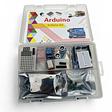
Use the components named in this tutorial. A computer and any additional power supply are not included.
x1
$64.70
In stock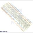
Use this larger board in place of the kit’s 400-contact breadboard, to keep component bodies and jumper connections clear.
x1
$8.90
In stockProject Summary
2 parts total
Unavailable items will be skipped
