

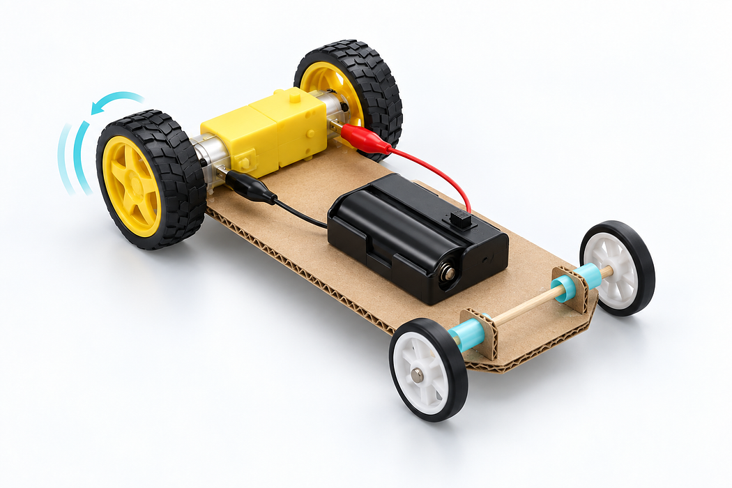
Build a moving vehicle with a TT geared motor
Explore a brushed motor and its gears in 3D, then build and test a lightweight two-AA vehicle. Designed for paired Year 5–6 STEM stations.
Investigate how a battery-powered motor changes electrical energy into rotation, then use that rotation to move a lightweight vehicle. Start with the interactive cutaway: inspect the coil, commutator, gears and dual output shaft; swap the battery leads to see why direction changes.
What success looks like
Each pair builds a circuit they can switch on and off, predicts the direction after reversing the leads, and makes a vehicle move under its own power. Students explain where electrical energy becomes mechanical energy and why a larger gear reduction can help move a loaded vehicle.
Teacher preparation
For 16 identical stations, prepare 16 dual-shaft TT motors in the 120:1 bare-tinned-lead variant, 16 switched two-AA holders with large alligator clips, and 32 AA cells, plus your existing wheels and light construction materials. Make one sample station before ordering 16: check that the clips grip the motor leads without touching, and that your wheels fit the motor's 3 mm double-D output shaft. The holder, cells and motor are separate products.
Use the 48:1 version to compare speed and load if you already have one. For a new two-AA vehicle set, the 120:1 version is the more suitable first choice. Performance depends on vehicle mass, wheel fit, friction, battery condition and surface; test one build before scaling up.
Step 1 — Look inside the motor and choose the gears
Switch between Assembled, Cutaway and Exploded. Open the case, then move the output-shaft slider. Watch the copper coil turn rapidly while the white gears slow the output shaft. Compare 48:1 and 120:1: at equal motor speed, the 120:1 output turns 2.5 times more slowly and has a higher ideal torque multiplication. Real torque is lower because gears lose energy to friction. Choose Vehicle example to inspect the classroom layout.
Discuss: Which gearbox would you test first when the motor must move a vehicle on two AA cells? Why?
Step 2 — Check the materials before wiring
At each pair's station, set out one dual-shaft TT gearmotor selected as 120:1 / Bare Tinned Leads, one switched 2×AA alligator-clip holder, two AA cells, lightweight chassis material, tape or a motor bracket, and wheels/free-axle materials. The white 65 mm TT wheel is an optional known-fit example; classroom wheels are fine if their hubs securely fit a 3 mm double-D TT shaft.
Test both output ends with the available wheel hubs. If only one hub fits, redesign around one driven wheel and stable free supports rather than forcing a loose or incompatible wheel. Keep the battery switch accessible and the clipped leads apart.
Step 3 — Build and test the simple motor circuit
- Keep the holder switch OFF. Place two AA cells in the holder, matching the printed polarity marks.
- Clip one holder lead to each separate bare-tinned motor lead. Make sure the metal jaws cannot touch each other or the opposite lead.
- Lift the motor clear of the table and switch ON. Observe the output shaft. Switch OFF before changing clips.
- Swap the two clips, then switch on again. Record the change in direction. In the 3D model, press Swap leads · reverse to compare.
Do not leave the shaft stalled or the leads shorted. If the clips cannot grip safely, have an adult prepare insulated lead extensions or use a different suitable clip; do not rely on a precarious contact.
Evidence: Sketch a circuit with the holder, switch and motor, and annotate both current direction and shaft direction for each polarity.
Step 4 — Build a lightweight chassis and free axle
- Cut a light, stiff chassis from cardboard or another classroom material. Leave room for the motor, its output wheel(s) and the battery holder.
- Mount the motor square to the chassis with a bracket or secure tape. Keep the output shaft free to rotate.
- If using a free axle, pass a skewer through a drinking-straw sleeve fixed to the chassis. The skewer must spin easily inside the straw. Attach compatible wheels so they do not rub the frame.
- Fix the battery holder securely, with its switch and cover accessible. Route the clips away from the gears and wheels.
The model's four-wheel layout shows one workable arrangement: the motor drives the rear wheels and a skewer/straw axle supports the front. Change the chassis to suit the wheels you already own. Verify wheel-hub fit before cutting all 16 chassis.
Step 5 — Test, measure and improve
- With the wheels lifted, switch on briefly. Check that the driven wheels turn freely, in the direction you predicted.
- Switch off, place the vehicle on a level floor and clear a short straight path. Switch on and observe.
- Record whether it starts by itself, how far it travels in five seconds, and whether it travels straight. Change one feature at a time—mass, wheel alignment, axle friction or battery position—and repeat.
- Reverse the clips with power off and test the opposite direction.
Challenge: Compare a 48:1 and 120:1 motor on otherwise similar light vehicles. Predict which will be faster unloaded and which is more likely to start a heavier load; test rather than assuming the ideal ratios predict exact results.
Step 6 — Troubleshoot and explain your design
If the motor does not turn
Switch off and check cell orientation, battery condition, the holder switch and the two separate clip contacts. Inspect for clips touching or a jammed shaft.
If the motor turns but the vehicle does not move
Check that the wheel hub grips the double-D shaft, the wheels touch the floor, and the free axle spins without rubbing. Reduce weight and friction. A 48:1 unit may turn quickly without enough useful starting force for this particular build; retry with the 120:1 option.
If the vehicle veers
Check wheel diameters, axle alignment and uneven rubbing. Change one variable and measure again.
Explain it
Use a labelled drawing to trace energy from the AA cells through the motor windings and magnetic field, across the reduction gears, to the output shaft and wheels. Explain why swapping leads reverses rotation and why the 120:1 train trades output speed for greater ideal torque multiplication.
Extension: Explore how wheel diameter changes distance per shaft turn. If testing a higher supply later, use only a holder within the motor's 3–6 V range and recheck current, heating and classroom safety with an adult.
Parts List
Required Parts (2)
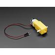
48:1 / 10cm Male Dupont
Select the dual-shaft 120:1 / Bare Tinned Leads option for the two-AA vehicle.
x1
$5.90
In stock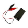
Add two AA cells. Use the switch and keep the clips on separate motor leads.
x1
$1.70
In stockProject Summary
2 parts total
Unavailable items will be skipped
