

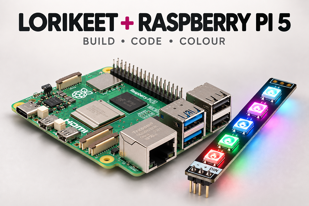
Light the Lorikeet with Raspberry Pi 5
Connect five addressable RGB LEDs with an interactive 3D build, complete code and colour experiments.
Build a five-pixel colour light, follow every connection in 3D, then run a program that changes all five LEDs from red to green to blue once a second. Learn which wire supplies power, which carries data, and why a colour change needs an explicit send command.
Bring the host board and USB connection described in the first step. The shopping list below contains the additional breadboard circuit parts.
Step 1 — Gather the parts and identify the input
A Raspberry Pi 5 running Raspberry Pi OS Bookworm or later, its recommended USB-C power supply, and terminal access through a monitor/keyboard or SSH. This guide assumes you can sign in to the Pi.
- 1 × Little Bird Lorikeet WS2812B Rainbow Board (five LEDs, input header soldered).
- 1 × 830-contact solderless breadboard; 1 × 330 Ω resistor; jumper leads.
- A computer and the correct data-capable USB cable. No battery or separate LED supply is required for this single-board, low-brightness test.
- 1 × 74AHCT125 DIP-14 level shifter, plus 1 × 100 nF ceramic capacitor.
- Male-to-male jumpers for the breadboard. The Pi 5 also needs three female-to-male jumpers for its GPIO header.
Unplug all power before adding or moving wires. Match the printed −, + and DIN labels on the Lorikeet input header; the pads at the other end are the output for another board. Never connect 5 V to a 3.3 V GPIO. Use one board and keep LEVEL at 24 for the first USB-powered test. Do not power the LEDs from a GPIO pin or the 3V3 rail.
For longer chains or high brightness, use a suitably rated external regulated 5 V LED supply and a common ground. Keep its positive output separate from the host 5 V rail. Adafruit recommends a bulk capacitor at an external LED supply; do not scale this small USB-powered circuit without reviewing the power requirements.
Step 2 — Follow the complete 3D build
Press Play to follow the connections, or rotate and zoom to inspect a pin. The individual actions below let you work at your own pace. The final colour animation shows the supplied program’s sequence; it does not run edits from the code editor.
Loading assembly…
Shut down the Pi and unplug its U S B-C supply. Identify physical pin 1 on the general purpose input and output header before connecting anything. Insert the Lorikeet input header into A55, A56 and A57. Its minus pin is ground, plus is five volts, and DIN receives data. Keep the five L E Ds facing up; the board extends beyond the breadboard. Insert the 330 ohm resistor with one lead in D53 and the other in D57. The D57 strip already connects to Lorikeet DIN. Either resistor orientation works. Insert the 74AHCT125 across the centre channel. The pin-one dot is on the upper right: pin one goes into E48, pin seven into E42, and pin fourteen into F48. Use AHCT, not HC. Insert the 100 nanofarad ceramic capacitor into H49 and H50. It is not polarised. Short wires will connect it across the buffer supply. Connect buffer output pin three to the free end of the 330 ohm resistor. The buffer raises the data level to five volts. Connect the Raspberry Pi 5 Model B’s 6 ground pin to the ground rail. Every signal in this circuit needs the same ground reference. Connect the Raspberry Pi 5 Model B’s 2 5 volts pin to the positive rail. Keep the supply unplugged until every connection is checked. Connect the ground rail to the Lorikeet board’s ground pin, using a free hole on the same strip as the Lorikeet minus pin. Connect the positive rail to the Lorikeet board’s 5 volts pin. This is five volts for the L E Ds; it is not a general purpose input and output signal. Connect buffer pin seven to ground. Connect buffer pin fourteen to five volts. Connect pin one to ground to enable the first buffer channel. Connect pin four to five volts to disable the unused second channel. Connect pin ten to five volts to disable the unused third channel. Connect pin thirteen to five volts to disable the unused fourth channel. Connect unused input pin five to ground so it cannot float. Connect unused input pin nine to ground. Connect unused input pin twelve to ground. Connect one capacitor lead to the five volt supply at buffer pin fourteen. Connect the other capacitor lead to buffer ground, pin seven. This capacitor helps stabilise the buffer supply. Connect the Raspberry Pi 5 Model B’s 19 GPIO10 pin to buffer input pin two. This side carries the three point three volt signal. Check five volts, ground and the data path. Then connect power and run the code below. All five L E Ds should show red, green and blue, changing once a second.
Step 3 — Place Raspberry Pi 5 Model B
Shut down the Pi and unplug its USB-C supply. Identify physical pin 1 on the GPIO header before connecting anything.
Loading assembly…
Shut down the Pi and unplug its U S B-C supply. Identify physical pin 1 on the general purpose input and output header before connecting anything.
Step 4 — Place Little Bird Lorikeet · five WS2812B LEDs
Insert the Lorikeet input header into A55, A56 and A57. Its minus pin is ground, plus is five volts, and DIN receives data. Keep the five LEDs facing up; the board extends beyond the breadboard.
Exact breadboard holes
- lorikeet · GND → A55
- lorikeet · 5V → A56
- lorikeet · DIN → A57
Loading assembly…
Insert the Lorikeet input header into A55, A56 and A57. Its minus pin is ground, plus is five volts, and DIN receives data. Keep the five L E Ds facing up; the board extends beyond the breadboard.
Step 5 — Place 330 Ω resistor
Insert the 330 ohm resistor with one lead in D53 and the other in D57. The D57 strip already connects to Lorikeet DIN. Either resistor orientation works.
Exact breadboard holes
- resistor · Pin 0 → D53
- resistor · Pin 1 → D57
Loading assembly…
Insert the 330 ohm resistor with one lead in D53 and the other in D57. The D57 strip already connects to Lorikeet DIN. Either resistor orientation works.
Step 6 — Place 74AHCT125 · 3.3V to 5V buffer
Insert the 74AHCT125 across the centre channel. The pin-one dot is on the upper right: pin one goes into E48, pin seven into E42, and pin fourteen into F48. Use AHCT, not HC.
Exact breadboard holes
- buffer · 1OE → E48
- buffer · 1A → E47
- buffer · 1Y → E46
- buffer · 2OE → E45
- buffer · 2A → E44
- buffer · 2Y → E43
- buffer · GND → E42
- buffer · 3Y → F42
- buffer · 3A → F43
- buffer · 3OE → F44
- buffer · 4Y → F45
- buffer · 4A → F46
- buffer · 4OE → F47
- buffer · VCC → F48
Loading assembly…
Insert the 74AHCT125 across the centre channel. The pin-one dot is on the upper right: pin one goes into E48, pin seven into E42, and pin fourteen into F48. Use AHCT, not HC.
Step 7 — Place 100 nF ceramic capacitor
Insert the 100 nanofarad ceramic capacitor into H49 and H50. It is not polarised. Short wires will connect it across the buffer supply.
Exact breadboard holes
- bypass · 0 → H49
- bypass · 1 → H50
Loading assembly…
Insert the 100 nanofarad ceramic capacitor into H49 and H50. It is not polarised. Short wires will connect it across the buffer supply.
Step 8 — Connect A46 → A53
Connect buffer output pin three to the free end of the 330 ohm resistor. The buffer raises the data level to five volts.
| Connect | To |
|---|---|
| A46 | A53 |
Loading assembly…
Connect buffer output pin three to the free end of the 330 ohm resistor. The buffer raises the data level to five volts.
Step 9 — Connect Raspberry Pi 5 Model B 6 GND → T− rail 15
Connect the Raspberry Pi 5 Model B’s 6 GND pin to the ground rail. Every signal in this circuit needs the same ground reference.
| Connect | To |
|---|---|
| Raspberry Pi 5 Model B 6 GND | T− rail 15 |
Loading assembly…
Connect the Raspberry Pi 5 Model B’s 6 ground pin to the ground rail. Every signal in this circuit needs the same ground reference.
Step 10 — Connect Raspberry Pi 5 Model B 2 5V → T+ rail 14
Connect the Raspberry Pi 5 Model B’s 2 5V pin to the positive rail. Keep the supply unplugged until every connection is checked.
| Connect | To |
|---|---|
| Raspberry Pi 5 Model B 2 5V | T+ rail 14 |
Loading assembly…
Connect the Raspberry Pi 5 Model B’s 2 5 volts pin to the positive rail. Keep the supply unplugged until every connection is checked.
Step 11 — Connect T− rail 45 → B55
Connect the ground rail to the Lorikeet board’s ground pin, using a free hole on the same strip as the Lorikeet minus pin.
| Connect | To |
|---|---|
| T− rail 45 | B55 |
Loading assembly…
Connect the ground rail to the Lorikeet board’s ground pin, using a free hole on the same strip as the Lorikeet minus pin.
Step 12 — Connect T+ rail 45 → B56
Connect the positive rail to the Lorikeet board’s 5V pin. This is five volts for the LEDs; it is not a GPIO signal.
| Connect | To |
|---|---|
| T+ rail 45 | B56 |
Loading assembly…
Connect the positive rail to the Lorikeet board’s 5 volts pin. This is five volts for the L E Ds; it is not a general purpose input and output signal.
Step 13 — Connect A42 → T− rail 34
Connect buffer pin seven to ground.
| Connect | To |
|---|---|
| A42 | T− rail 34 |
Loading assembly…
Connect buffer pin seven to ground.
Step 14 — Connect J48 → T+ rail 39
Connect buffer pin fourteen to five volts.
| Connect | To |
|---|---|
| J48 | T+ rail 39 |
Loading assembly…
Connect buffer pin fourteen to five volts.
Step 15 — Connect A48 → T− rail 39
Connect pin one to ground to enable the first buffer channel.
| Connect | To |
|---|---|
| A48 | T− rail 39 |
Loading assembly…
Connect pin one to ground to enable the first buffer channel.
Step 16 — Connect A45 → T+ rail 36
Connect pin four to five volts to disable the unused second channel.
| Connect | To |
|---|---|
| A45 | T+ rail 36 |
Loading assembly…
Connect pin four to five volts to disable the unused second channel.
Step 17 — Connect J44 → T+ rail 35
Connect pin ten to five volts to disable the unused third channel.
| Connect | To |
|---|---|
| J44 | T+ rail 35 |
Loading assembly…
Connect pin ten to five volts to disable the unused third channel.
Step 18 — Connect J47 → T+ rail 38
Connect pin thirteen to five volts to disable the unused fourth channel.
| Connect | To |
|---|---|
| J47 | T+ rail 38 |
Loading assembly…
Connect pin thirteen to five volts to disable the unused fourth channel.
Step 19 — Connect A44 → T− rail 35
Connect unused input pin five to ground so it cannot float.
| Connect | To |
|---|---|
| A44 | T− rail 35 |
Loading assembly…
Connect unused input pin five to ground so it cannot float.
Step 20 — Connect J43 → T− rail 33
Connect unused input pin nine to ground.
| Connect | To |
|---|---|
| J43 | T− rail 33 |
Loading assembly…
Connect unused input pin nine to ground.
Step 21 — Connect J46 → T− rail 37
Connect unused input pin twelve to ground.
| Connect | To |
|---|---|
| J46 | T− rail 37 |
Loading assembly…
Connect unused input pin twelve to ground.
Step 22 — Connect J49 → I48
Connect one capacitor lead to the five volt supply at buffer pin fourteen.
| Connect | To |
|---|---|
| J49 | I48 |
Loading assembly…
Connect one capacitor lead to the five volt supply at buffer pin fourteen.
Step 23 — Connect J50 → B42
Connect the other capacitor lead to buffer ground, pin seven. This capacitor helps stabilise the buffer supply.
| Connect | To |
|---|---|
| J50 | B42 |
Loading assembly…
Connect the other capacitor lead to buffer ground, pin seven. This capacitor helps stabilise the buffer supply.
Step 24 — Connect Raspberry Pi 5 Model B 19 GPIO10 → A47
Connect the Raspberry Pi 5 Model B’s 19 GPIO10 pin to buffer input pin two. This side carries the three point three volt signal.
| Connect | To |
|---|---|
| Raspberry Pi 5 Model B 19 GPIO10 | A47 |
Loading assembly…
Connect the Raspberry Pi 5 Model B’s 19 GPIO10 pin to buffer input pin two. This side carries the three point three volt signal.
Step 25 — Run the colour sequence
Check five volts, ground and the DIN path. Then connect power and run the code below. All five LEDs should show red, green and blue, changing once a second.
Loading assembly…
Check five volts, ground and the data path. Then connect power and run the code below. All five L E Ds should show red, green and blue, changing once a second.
Step 26 — Check the complete circuit
Before applying power, trace ground, five volts and data separately. The resistor must be in the data path, not between 5 V and the Lorikeet. No jumper should bridge the positive and ground rails.
The buffer is one-way: GPIO enters pin 2 (1A), leaves pin 3 (1Y) at 5 V, then passes through 330 Ω to DIN. Unused outputs 6, 8 and 11 remain unconnected. Unused inputs are grounded and their enable pins are high.
Step 27 — Set up SPI on Raspberry Pi 5
Use SPI0 MOSI: GPIO10, physical pin 19, through the AHCT125. Physical pin 2 supplies 5 V and pin 6 is ground. Reserve SPI0 for the LEDs during this project; do not share its clock/data with another SPI device. No wire goes from the Pi clock or chip-select pins to the Lorikeet.
The Cast below was recorded on a Raspberry Pi 5. Follow it in a terminal on your Pi. Enable SPI with sudo raspi-config nonint do_spi 0; sudo dtparam spi=on applies it now. A reboot also applies the saved setting. Confirm /dev/spidev0.0 exists before continuing. A device named spidev10.0 alone is not SPI0.
Step 28 — Copy the setup commands
# Run on your Raspberry Pi 5, in its terminal.
sudo raspi-config nonint do_spi 0
sudo dtparam spi=on
ls /dev/spidev0.*
sudo apt-get install -y python3-venv python3-lgpio
mkdir -p ~/lorikeet
cd ~/lorikeet
python3 -m venv --system-site-packages .venv
source .venv/bin/activate
python -m pip install adafruit-blinka adafruit-circuitpython-neopixel-spi
python -c "import board, neopixel_spi; print('Pi SPI and NeoPixel libraries are ready')"
# Save the supplied Python program here as lorikeet_pi.py, then:
python lorikeet_pi.py
# Press Ctrl+C to stop and clear the LEDs.
Run these commands on the Pi. The virtual environment uses system site packages so Raspberry Pi OS’s lgpio binding is available. Packages installed by pip stay in the project environment. If a package is not found by apt, run sudo apt-get update and retry. Your user needs membership of the spi and gpio groups; Raspberry Pi OS normally supplies this.
Step 29 — Save and run the Python program
"""Five Lorikeet LEDs on Pi 5 SPI0 MOSI (GPIO10 / physical pin 19).
Use a 5V-powered 74AHCT125 and a 330-ohm series data resistor.
"""
import time
import board
import neopixel_spi

LED_COUNT = 5
LEVEL = 24
HOLD_SECONDS = 1.0
spi = board.SPI()
pixels = neopixel_spi.NeoPixel_SPI(
    spi, LED_COUNT, brightness=1.0, auto_write=False,
    pixel_order=neopixel_spi.GRB,
)

try:
    print("Sending red, green and blue to five LEDs. Press Ctrl+C to stop.")
    while True:
        for colour in ((LEVEL, 0, 0), (0, LEVEL, 0), (0, 0, LEVEL)):
            pixels.fill(colour)             # Tuples are (red, green, blue).
            pixels.show()                  # Encode and send over SPI MOSI.
            time.sleep(HOLD_SECONDS)
except KeyboardInterrupt:
    print("Stopped; clearing the LEDs.")
finally:
    pixels.fill((0, 0, 0))
    pixels.show()
    pixels.deinit()
    spi.deinit()
Save this file as ~/lorikeet/lorikeet_pi.py. In the terminal run cd ~/lorikeet, source .venv/bin/activate, then python lorikeet_pi.py. Press Ctrl+C to stop and send an all-off frame. Use this SPI version on Pi 5 rather than older PWM/DMA NeoPixel examples for other Pi models.
Step 30 — Understand the program
Each LED package contains red, green and blue emitters plus a controller. The host sends one timed stream into DIN. The first pixel uses the first colour value, then forwards the remaining values along the board. Each LED keeps its last value until a new frame arrives; one data wire can therefore control all five independently.
board.SPI() opens the board’s default SPI0 bus. The NeoPixel_SPI library encodes the WS2812B timing into bytes and transmits them on MOSI (GPIO10). The AHCT125 changes the voltage level, not the colour values or timing. The Lorikeet does not use a separate clock wire.
LED_COUNT = 5 allocates five pixels. LEVEL = 24 limits each selected colour channel on its 0–255 scale. brightness=1.0 leaves those already-small values unchanged. auto_write=False waits for an explicit show() so a complete colour frame is sent together; pixel_order=GRB handles the wire order.
The nested loops repeatedly fill all five pixels with red, green and blue, holding each for HOLD_SECONDS = 1.0. For the first tuple, (24, 0, 0), the library sends five identical red pixels. Ctrl+C raises KeyboardInterrupt; the handler prints a message, then finally sends black and releases the pixels and bus.
The Cast confirms software installation, SPI access and program execution. To check the electrical result, observe your connected Lorikeet: the terminal cannot confirm that LEDs actually lit.
Step 31 — Test, predict and change one thing
Success check: all five LEDs change together, red → green → blue, with one second per colour and three seconds per full cycle. Let three cycles run and check for flicker before changing anything.
Predict what happens if you halve the hold time. Change only HOLD_MS to 500 (Arduino/Pico), or HOLD_SECONDS to 0.5 (Pi), run again and time one complete red–green–blue cycle. Record your prediction and observation.
Next, keep the green value at zero and use equal red and blue values. Predict the colour before trying it. Finally, explain why changing the saved colour without calling show() or write() leaves the LEDs unchanged.
Check your reasoning
A cycle falls from three seconds to 1.5 seconds. Equal red and blue make magenta. fill() changes a buffer in the host; show()/write() transmits that buffer, so the LEDs cannot see an unsent change.
Step 32 — Find and fix a problem
- No lights: disconnect power; check − to ground, + to 5 V and data to DIN rather than DOUT. Confirm the resistor shares DIN’s strip and LED_COUNT is 5. Reconnect and rerun.
- Flicker or random colours: check the shared ground and shorten the data wiring. On Pico/Pi, check AHCT125 pin 14 to 5 V, pin 7 to ground and active-low pin 1 to ground. Do not substitute a 74HC125.
- Wrong colours: keep the library’s GRB wire order but supply colour tuples/arguments in red, green, blue order. If just one pixel fails, test the first pixel before suspecting the software.
- The board resets: unplug it and check for a short. Return LEVEL to 24 and test only one Lorikeet. Do not keep increasing brightness to diagnose a power fault.
Pi import/SPI errors: activate the project environment; ensure it was created with --system-site-packages and python3-lgpio is installed. Check SPI is enabled and you can read/write /dev/spidev0.0. Do not run the program with sudo as a substitute for fixing permissions.
Step 33 — Keep exploring
Parts List
Required Parts (7)

Five WS2812B LEDs. Use the input header marked −, + and DIN.
x1
$2.00
In stock![74AHCT125 - Quad Level-Shifter (3V to 5V) [74AHCT125]](https://littlebirdelectronics.com.au/rails/active_storage/representations/redirect/BAh7BkkiC19yYWlscwY6BkVUewdJIglkYXRhBjsAVGkCpnJJIghwdXIGOwBUSSIMYmxvYl9pZAY7AEY=--e1ef1f697e3fb0453a848a8b32408f39488f5e35/BAh7BkkiC19yYWlscwY6BkVUewdJIglkYXRhBjsAVHsHOgtmb3JtYXRJIghqcGcGOwBUOhNyZXNpemVfdG9fZmlsbFsHaXVpdUkiCHB1cgY7AFRJIg52YXJpYXRpb24GOwBG--ea68efa75a9e9b4d35a5bf37c189565153bcf4b1/image_7e6b4bc4-2541-47c5-8e85-8dabc3e95e00.jpg)
DIP-14 AHCT buffer, powered at 5 V. Also use a 100 nF bypass capacitor.
x1
$3.15
Out of stock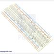
Use one full-size 830-contact board for the numbered 3D layout.
x1
$8.90
In stock
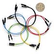
Use five leads for Arduino, seventeen for Pico, or fourteen plus three female-to-male leads for Pi 5.
x1
$10.60
In stock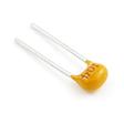
Use one 100 nF (0.1 µF) capacitor across the AHCT125 supply.
x1
$0.65
In stock
Use three leads from the Pi GPIO header to the breadboard.
x1
$2.50
In stockProject Summary
7 parts total
Unavailable items will be skipped
