

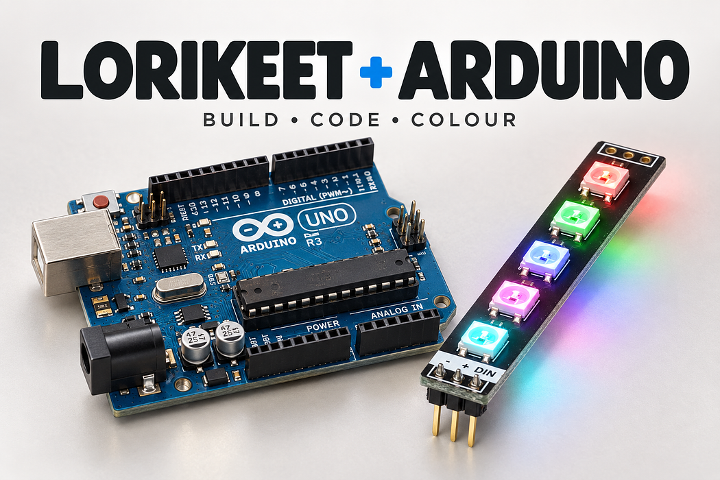
Light the Lorikeet with Arduino
Connect five addressable RGB LEDs with an interactive 3D build, complete code and colour experiments.
Build a five-pixel colour light, follow every connection in 3D, then run a program that changes all five LEDs from red to green to blue once a second. Learn which wire supplies power, which carries data, and why a colour change needs an explicit send command.
Bring the host board and USB connection described in the first step. The shopping list below contains the additional breadboard circuit parts.
Step 1 — Gather the parts and identify the input
An Arduino Uno R3 or Little Bird Uno compatible with 5 V logic, a USB data cable and desktop Chrome. This guide starts with basic breadboard use; you do not need prior NeoPixel code.
- 1 × Little Bird Lorikeet WS2812B Rainbow Board (five LEDs, input header soldered).
- 1 × 830-contact solderless breadboard; 1 × 330 Ω resistor; jumper leads.
- A computer and the correct data-capable USB cable. No battery or separate LED supply is required for this single-board, low-brightness test.
Unplug all power before adding or moving wires. Match the printed −, + and DIN labels on the Lorikeet input header; the pads at the other end are the output for another board. Never connect 5 V to a 3.3 V GPIO. Use one board and keep LEVEL at 24 for the first USB-powered test. Do not power the LEDs from a GPIO pin or the 3V3 rail.
For longer chains or high brightness, use a suitably rated external regulated 5 V LED supply and a common ground. Keep its positive output separate from the host 5 V rail. Adafruit recommends a bulk capacitor at an external LED supply; do not scale this small USB-powered circuit without reviewing the power requirements.
Step 2 — Follow the complete 3D build
Press Play to follow the connections, or rotate and zoom to inspect a pin. The individual actions below let you work at your own pace. The final colour animation shows the supplied program’s sequence; it does not run edits from the code editor.
Loading assembly…
Insert the Lorikeet input header into A55, A56 and A57. Its minus pin is ground, plus is five volts, and DIN receives data. Keep the five L E Ds facing up; the board extends beyond the breadboard. Insert the 330 ohm resistor with one lead in D53 and the other in D57. The D57 strip already connects to Lorikeet DIN. Either resistor orientation works. Connect Arduino digital pin three to the free end of the 330 ohm resistor. The resistor leads to DIN. Connect Arduino ground to the ground rail. Every signal in this circuit needs the same ground reference. Connect the Arduino’s five volt output to the positive rail. Keep the supply unplugged until every connection is checked. Connect the ground rail to the Lorikeet board’s ground pin, using a free hole on the same strip as the Lorikeet minus pin. Connect the positive rail to the Lorikeet board’s 5 volts pin. This is five volts for the L E Ds; it is not a general purpose input and output signal. Check five volts, ground and the data path. Then connect power and run the code below. All five L E Ds should show red, green and blue, changing once a second.
Step 3 — Place Little Bird Lorikeet · five WS2812B LEDs
Insert the Lorikeet input header into A55, A56 and A57. Its minus pin is ground, plus is five volts, and DIN receives data. Keep the five LEDs facing up; the board extends beyond the breadboard.
Exact breadboard holes
- lorikeet · GND → A55
- lorikeet · 5V → A56
- lorikeet · DIN → A57
Loading assembly…
Insert the Lorikeet input header into A55, A56 and A57. Its minus pin is ground, plus is five volts, and DIN receives data. Keep the five L E Ds facing up; the board extends beyond the breadboard.
Step 4 — Place 330 Ω resistor
Insert the 330 ohm resistor with one lead in D53 and the other in D57. The D57 strip already connects to Lorikeet DIN. Either resistor orientation works.
Exact breadboard holes
- resistor · Pin 0 → D53
- resistor · Pin 1 → D57
Loading assembly…
Insert the 330 ohm resistor with one lead in D53 and the other in D57. The D57 strip already connects to Lorikeet DIN. Either resistor orientation works.
Step 5 — Connect Uno D3 PWM → A53
Connect Arduino digital pin three to the free end of the 330 ohm resistor. The resistor leads to DIN.
| Connect | To |
|---|---|
| Uno D3 PWM | A53 |
Loading assembly…
Connect Arduino digital pin three to the free end of the 330 ohm resistor. The resistor leads to DIN.
Step 6 — Connect Uno GND → T− rail 11
Connect Arduino ground to the ground rail. Every signal in this circuit needs the same ground reference.
| Connect | To |
|---|---|
| Uno GND | T− rail 11 |
Loading assembly…
Connect Arduino ground to the ground rail. Every signal in this circuit needs the same ground reference.
Step 7 — Connect Uno 5V → T+ rail 15
Connect the Arduino’s five volt output to the positive rail. Keep the supply unplugged until every connection is checked.
| Connect | To |
|---|---|
| Uno 5V | T+ rail 15 |
Loading assembly…
Connect the Arduino’s five volt output to the positive rail. Keep the supply unplugged until every connection is checked.
Step 8 — Connect T− rail 45 → B55
Connect the ground rail to the Lorikeet board’s ground pin, using a free hole on the same strip as the Lorikeet minus pin.
| Connect | To |
|---|---|
| T− rail 45 | B55 |
Loading assembly…
Connect the ground rail to the Lorikeet board’s ground pin, using a free hole on the same strip as the Lorikeet minus pin.
Step 9 — Connect T+ rail 45 → B56
Connect the positive rail to the Lorikeet board’s 5V pin. This is five volts for the LEDs; it is not a GPIO signal.
| Connect | To |
|---|---|
| T+ rail 45 | B56 |
Loading assembly…
Connect the positive rail to the Lorikeet board’s 5 volts pin. This is five volts for the L E Ds; it is not a general purpose input and output signal.
Step 10 — Run the colour sequence
Check five volts, ground and the DIN path. Then connect power and run the code below. All five LEDs should show red, green and blue, changing once a second.
Loading assembly…
Check five volts, ground and the data path. Then connect power and run the code below. All five L E Ds should show red, green and blue, changing once a second.
Step 11 — Check the complete circuit
Before applying power, trace ground, five volts and data separately. The resistor must be in the data path, not between 5 V and the Lorikeet. No jumper should bridge the positive and ground rails.
Uno D3 → 330 Ω → DIN. Uno 5V → Lorikeet +. Uno GND → Lorikeet −. The Uno uses 5 V logic, so this build does not need a level shifter.
Step 12 — Program in English and upload from Chrome
Connect the Uno with a data-capable USB cable. In the English IDE choose Arduino Uno, use Verify, then Upload and select the Uno’s USB port when Chrome asks. Close other serial applications first. The Arduino C++ translation is already provided; you can inspect it beside the English instructions. The cloud compiler includes Adafruit NeoPixel.
For the desktop Arduino IDE instead, download the complete .ino below, install Adafruit NeoPixel from Library Manager, select Arduino Uno and your USB port, then Verify and Upload.
Step 13 — Complete Arduino sketch
#include <Adafruit_NeoPixel.h>

const byte DATA_PIN = 3;
const byte LED_COUNT = 5;
const byte LEVEL = 24;                 // Keep this first USB-powered test dim.
const unsigned long HOLD_MS = 1000;
Adafruit_NeoPixel pixels(LED_COUNT, DATA_PIN, NEO_GRB + NEO_KHZ800);

void setup() {
  pixels.begin();
  pixels.clear();
  pixels.show();
}

void showColour(byte red, byte green, byte blue) {
  pixels.fill(pixels.Color(red, green, blue));
  pixels.show();                       // Send the buffered colours to all five LEDs.
  delay(HOLD_MS);
}

void loop() {
  showColour(LEVEL, 0, 0);
  showColour(0, LEVEL, 0);
  showColour(0, 0, LEVEL);
}
This is the same program as the English IDE translation. Save it in a folder named lorikeet_arduino.
Step 14 — Understand the program
Each LED package contains red, green and blue emitters plus a controller. The host sends one timed stream into DIN. The first pixel uses the first colour value, then forwards the remaining values along the board. Each LED keeps its last value until a new frame arrives; one data wire can therefore control all five independently.
DATA_PIN = 3 matches D3; LED_COUNT = 5 matches the five packages. LEVEL = 24 is the intensity of the selected colour channel, on a 0–255 scale. HOLD_MS = 1000 holds each colour for one second. NEO_GRB + NEO_KHZ800 selects the wire order and signalling rate expected by these WS2812B LEDs.
setup() starts the library and sends an all-off frame once. loop() runs forever. Its three calls pass red, green and blue values into showColour(). That helper fills all five saved pixels, transmits them with show(), then waits.
Trace the first call: showColour(LEVEL, 0, 0) becomes showColour(24, 0, 0). All five red channels become 24; green and blue are zero. After one second, the next call replaces that frame with green. These deliberate delays suit this simple light; a future button-responsive project would use non-blocking timing.
Step 15 — Test, predict and change one thing
Success check: all five LEDs change together, red → green → blue, with one second per colour and three seconds per full cycle. Let three cycles run and check for flicker before changing anything.
Predict what happens if you halve the hold time. Change only HOLD_MS to 500 (Arduino/Pico), or HOLD_SECONDS to 0.5 (Pi), run again and time one complete red–green–blue cycle. Record your prediction and observation.
Next, keep the green value at zero and use equal red and blue values. Predict the colour before trying it. Finally, explain why changing the saved colour without calling show() or write() leaves the LEDs unchanged.
Check your reasoning
A cycle falls from three seconds to 1.5 seconds. Equal red and blue make magenta. fill() changes a buffer in the host; show()/write() transmits that buffer, so the LEDs cannot see an unsent change.
Step 16 — Find and fix a problem
- No lights: disconnect power; check − to ground, + to 5 V and data to DIN rather than DOUT. Confirm the resistor shares DIN’s strip and LED_COUNT is 5. Reconnect and rerun.
- Flicker or random colours: check the shared ground and shorten the data wiring. On Pico/Pi, check AHCT125 pin 14 to 5 V, pin 7 to ground and active-low pin 1 to ground. Do not substitute a 74HC125.
- Wrong colours: keep the library’s GRB wire order but supply colour tuples/arguments in red, green, blue order. If just one pixel fails, test the first pixel before suspecting the software.
- The board resets: unplug it and check for a short. Return LEVEL to 24 and test only one Lorikeet. Do not keep increasing brightness to diagnose a power fault.
Step 17 — Keep exploring
Parts List
Required Parts (4)

Five WS2812B LEDs. Use the input header marked −, + and DIN.
x1
$2.00
In stock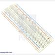
Use one full-size 830-contact board for the numbered 3D layout.
x1
$8.90
In stock
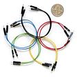
Use five leads for Arduino, seventeen for Pico, or fourteen plus three female-to-male leads for Pi 5.
x1
$10.60
In stockProject Summary
4 parts total
Unavailable items will be skipped
