

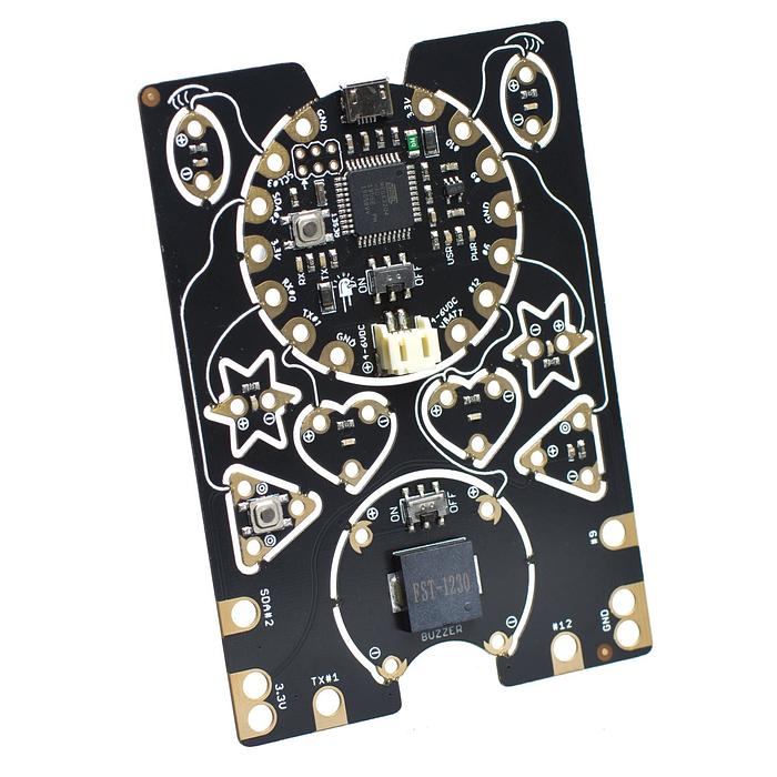
Play notes on the EagLED buzzer
Drive the built-in piezo and explain the relationship between frequency, duration and its shared LED pin.
Drive the built-in piezo and explain the relationship between frequency, duration and its shared LED pin.
Designed for the intact EagLED v1.2 with buzzer. Start with USB power; no cutting or sewing is required.
Step 1 — Prepare the intact EagLED
Use an intact black EagLED v1.2 with buzzer, a micro-USB data cable and a computer. The LEDs, button and light sensor are already connected by PCB traces. You do not need jumper wires, a breadboard, external resistors or a separate Arduino.
Keep the board uncut for this project. Place it on a dry, non-conductive surface. Leave the battery socket empty, connect USB and move the main board switch to ON. Move the separate switch beside the buzzer to ON.
The 3D view follows this starter program and its controls. It illustrates the mechanism; it does not execute changes made in the code editor or measure a connected board.
The original buzzer datasheet specifies a 12 × 12 × 3 mm package. Its response is strongest around its specified resonance; use a comfortable listening distance.
Step 2 — Explore the result in 3D
Switch the buzzer ON and press Play. C5, E5 and G5 each sound for 300 ms with 200 ms gaps, then a 500 ms rest. Enable Hear the notes if you want browser audio. Drag to orbit, inspect a named component, and use Top or Underside to follow the real board layout.
Step 3 — Program your EagLED
The English IDE below opens with Little Bird EagLED and Arduino C++ selected. Read the English instructions beside the supplied program, then press Verify to compile it for this board.
To program your physical board, download the same sketch below and open it in Arduino IDE. Install the Little Bird AVR board package, choose Little Bird EagLED and its USB port, then Verify and Upload. Follow the EagLED setup guide if this is your first upload. Upload replaces the factory light pattern.
EagLED uses an ATmega32U4 at 8 MHz. Do not choose Uno or a 16 MHz Leonardo profile. Its USB port can change while the bootloader is active. If upload fails, check the selected port and retry after pressing the centre board’s reset button. The triangular project button is not reset. Close any browser serial connection before uploading from Arduino IDE.
Step 4 — Keep a copy of the complete program
const byte BUZZER_PIN = 12;
const unsigned int NOTES[] = {523, 659, 784};
const unsigned long NOTE_MS = 300;
const unsigned long GAP_MS = 200;
void setup() { pinMode(BUZZER_PIN, OUTPUT); }
void loop() {
  for (byte i = 0; i < 3; i++) {
    tone(BUZZER_PIN, NOTES[i]);
    delay(NOTE_MS);
    noTone(BUZZER_PIN);
    digitalWrite(BUZZER_PIN, LOW);
    delay(GAP_MS);
  }
  delay(500);
}
This is the same complete Arduino C++ program used by the English IDE. Copy it or download the .ino file.
Step 5 — Understand the program
The FST-1230 is a passive piezo transducer. tone(pin, frequency) makes an alternating square wave; a steady HIGH will not sustain a musical note. Frequency is in hertz (cycles per second), whereas NOTE_MS and GAP_MS are milliseconds.
tone(BUZZER_PIN, NOTES[i]);
delay(NOTE_MS);
noTone(BUZZER_PIN);
digitalWrite(BUZZER_PIN, LOW);
The array holds three frequencies. tone starts the waveform, the first delay lets it sound, noTone stops it, and LOW leaves a known quiet output state. On the intact board, D12 also drives the right-heart LED; it can look dimly lit during the waveform. SW4 opens only the buzzer branch. Browser audio illustrates pitch; it does not reproduce the acoustic response of your physical piezo.
Step 6 — Work through one case
| Time | D12 / sound | Right heart |
|---|---|---|
| 0–300 ms | 523 Hz · C5 | Rapid pulses / average glow |
| 300–500 ms | LOW · gap | Off |
| 500–800 ms | 659 Hz · E5 | Average glow |
| 1000–1300 ms | 784 Hz · G5 | Average glow |
| 1300–2000 ms | LOW · gap + rest | Off |
Step 7 — Test it on your board
Switch the buzzer ON and press Play. C5, E5 and G5 each sound for 300 ms with 200 ms gaps, then a 500 ms rest. Enable Hear the notes if you want browser audio.
Check the physical output after uploading. Successful compilation confirms syntax and board compatibility; the 3D illustration cannot confirm your board’s USB connection or electrical operation.
Step 8 — Predict, change and compare
Predict the change if you double only NOTES[0] from 523 to 1046. Keep NOTE_MS and GAP_MS fixed, upload and compare the first note with the unchanged second note. Then separately change NOTE_MS to 600 and explain which property changes. Restore the original values between trials.
Check your reasoning after trying it
Doubling frequency raises the first note by one octave while keeping its duration. Increasing NOTE_MS changes duration without changing pitch. The physical buzzer’s loudness depends on frequency; it is not guaranteed to sound equally loud at all three notes.
Step 9 — Find and fix a problem
Silent hardware: check the lower buzzer switch is ON and BUZZER_PIN is 12. Legacy detached-speaker tutorials use other pins; they do not describe this intact v1.2 connection. The right heart glows too: that is the actual shared D12 circuit. Only a click: use tone(), not a steady digitalWrite(HIGH).
Nothing responds: check the main switch, the power indicator and a known data-capable USB cable. Confirm the EagLED board profile and USB port. If the board has already been snipped apart, its original connections are broken: follow a separate sewable wiring project before using this intact-board sketch.
Step 10 — Keep exploring
Continue through the EagLED experiments or open the full board explorer. The original EagLED schematic and manufacturing files document the pin connections.
Parts List
Required Parts (1)
Keep the board intact. Also bring a micro-USB data cable and computer. No additional sensor, LED, Arduino or breadboard is required.
x1
$34.35
In stockProject Summary
1 part total
Unavailable items will be skipped
