

Build a pedestrian crossing
Request a crossing with D7, sequence vehicle lights, and add Australian-style audible pedestrian feedback.
Step 1 — Predict the sequence
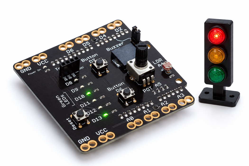
Build a button-operated pedestrian crossing. The three-colour module controls vehicles; shield D8 means WALK, D13 means WAIT, and D12 confirms a request. Predict why a button press cannot immediately stop traffic.
This tabletop model uses shortened teaching timings and Australian-style slow locator ticks and faster walk pulses.
Before you begin
Before running: enum gives names to states; enter changes phase and stores started. now-started is elapsed time. D6 is an output: do not press its shield button.
Your goal: Model behaviour with named states. Show this with a prediction, a tested change and an explanation using the program’s names.
Retrieve one idea: what input, state or output did you change in the previous project?
Need a reminder? Connect and blink an external LED.
Step 2 — Identify the matching contacts
Use the Little Bird traffic-light module. Select a signal below to find its matching contact on the shield. Separate the connector in 3D to inspect the pins, then test your matching before connecting the hardware.
Step 3 — Connect the traffic light
Disconnect USB and remove any separate LED circuit left on D5. Align all four module contacts with their matching socket contacts, then insert the module as one connector. Check that it is not shifted by one position and that ground matches ground before reconnecting USB.
D6 is also connected to the shield’s second button. Do not press the D6 button while this traffic-light program runs. The program drives that shared line as an output.
Loading assembly…
With power disconnected, match ground, red, yellow and green to the socket labels. Insert all four contacts together. Check the alignment before reconnecting power.
Step 4 — Program the shield
Choose Arduino Uno, then Verify and Upload the supplied sketch. The English instructions describe the same behaviour as the C++ beside them. Keep the USB cable connected while you test.
Step 5 — Request a crossing
Press D7 once. The request light comes on, but vehicles keep green for three seconds. Yellow follows for two seconds, then red for one second before WALK begins. Enable buzzer sound to hear the locator ticks, walk-start chirp and rapid walk pulses.
Vehicles stay red throughout WALK and clearance. A flashing WAIT means finish crossing; do not start. Holding or repeatedly pressing D7 must not shorten the waits.
Step 6 — Explain a state machine
Press Request crossing, then pause or move through the states. Match each change in the lights to phase, its elapsed timer and the highlighted condition.
Your turn: complete the trace
A request accepted at 0 leads to YELLOW at 3000 ms, ALL_RED at ___ and WALK at ___.
Compare your trace after trying
5000 ms and 6000 ms; each duration begins on entry to its own phase.
Inspect both the event condition and the output expressions, not only the list of durations.
Step 7 — Change a duration, then check the result
Increase WALK from five to eight seconds. Predict and measure the new request-to-ready time: eighteen seconds. Keep the all-red and clearance stages. Explain how the sound communicates the phase without requiring someone to see the lights.
- Press during WALK: the current sequence should finish without restarting.
- Hold D7 through the return to green: release and press again to make a new request.
- Sound missing: fit the buzzer jumper and enable sound in the embed.
- Wrong colours: disconnect USB and check R/D4, Y/D5, G/D6 and ground.
Run a controlled experiment
Build a state table of outputs and durations. Test a request during WALK and a held request. State the safety invariant and collect evidence at every transition.
- Save a copy of the working starter. Reset the board so stored state begins from the declared values.
- Write the expected result before editing. Change only the named factor; keep wiring and other settings fixed.
- Edit the C++ in the editor, Verify, then Upload to the connected Uno. The starter simulation does not execute your edited C++.
- Repeat the same input sequence. Record input, expected output, observed output and an explanation. Use labelled serial values where the sketch provides them.
- If the result differs, inspect the relevant condition and pin before changing another factor. Restore and upload the saved starter to recover.
Core task: explain one changed case. Optional extension: choose a boundary or timing case and justify the extra test. Use a paper trace or annotated screenshot when physical manipulation is inaccessible; distinguish predictions from measurements.
Independent check — try before revealing
What happens to a newly accepted press during WALK, and can vehicle green overlap WALK?
Hint
Inspect both the event condition and the output expressions, not only the list of durations.
Reasoning and feedback
The request is ignored because the phase must be READY. Green is selected only through REQUESTED; WALK selects red, so green and WALK do not overlap.
This is a tabletop model, not road control equipment. D6 drives the module green output: do not press the shield D6 button with this wiring.
If your explanation missed a condition or stored value, add that column to your trace and try a new input. A working upload alone does not answer this check.
Step 8 — A brief request can start a longer crossing
D7 is the pedestrian request. The program accepts a stable press only in READY, then enters REQUESTED.
Choose Cutaway. Move Button travel from released to fully pressed, hold it there, then release it. Watch the spring dome meet and leave the contact. Compare the D7 state and voltage at each point; on this shield a pressed button reads HIGH.
Predict and explain: Why can the crossing sequence continue after the requester releases the button?
Check your explanation
The program stores its phase and start time. A brief press changes that state; the timed phases then continue without needing a closed contact. Use D7 for the real request button: D6 is the traffic module’s green output in this build. The switch is momentary: its contact opens on release. Any remembered output belongs to the program. The cutaway shows a clean contact transition; real switches may bounce, which is why some sketches debounce their input.
Step 9 — Inside a crossing indicator
D4, D5 and D6 drive the traffic module’s red, yellow and green channels. Separate shield LEDs show pedestrian and request states. This red, two-lead LED exposes the same light-emitting principle used by the shield’s indicators; their colour and package can differ.
Choose Cutaway and find the tiny chip, reflector cup and bond wire. Leave Reverse polarity off, set Supply voltage to 5 V, then press Play blink. Watch current and light switch together. Pause before changing the supply to 3 V and then 1 V; the explorer keeps a 220 Ω resistor in series.
Predict and explain: If two channels must never be on together, can an LED enforce that rule by itself?
Check your explanation
No. The program must command the appropriate outputs for each phase. An LED only responds to its own forward current. The red LED explorer illustrates the junction principle, not the traffic module’s internal wiring or exact resistor values. The supply slider changes forward current during an on state. The lesson’s sketch separately determines which outputs are on and for how long.
Step 10 — How the crossing makes an audible cue
D3 produces locator ticks, a walk-start chirp and repeated walk pulses. Frequency and timing both carry information.
Choose Cutaway and press Play animation. Compare 440 Hz and 880 Hz using Change the pitch; use Tone off to enable the optional sound. The visible bending is slowed and enlarged. Pause, then drag Inspect one cycle through rising, steady and falling voltage.
Predict and explain: Which change makes a higher note, and which change makes more frequent beeps?
Check your explanation
Increasing tone frequency raises pitch; shortening the gap between tone commands increases beep rate. The same diaphragm produces both effects, controlled on different time scales. Changing voltage bends the bonded ceramic and brass diaphragm. Charge moves onto and off the electrodes, reversing during discharge; it does not pass through the ceramic. Try Electron flow to see the opposite direction convention for the same electrical behaviour.
Step 11 — Optional: investigate a moving barrier
A positional micro servo could move a lightweight model barrier in a later extension. It is an additional component, not part of the crossing build or sketch above. Start with this explorer; no hardware connection is needed for the investigation.
Choose Cutaway and set Target angle to 30°, then 120°. Watch the motor, reduction gears and measured angle. When it settles, press Nudge horn without changing the target. Repeat with Power off, then restore power.
Predict and explain: why does the powered horn return after a nudge? Choose two barrier positions you would associate with vehicles allowed and vehicles stopped; explain why adding a servo would require new output commands in the crossing sketch.
Check your explanation
The internal potentiometer reports actual position. The servo’s controller compares it with the target and drives the motor to reduce the error; without power it cannot make that correction. Its orange wire carries an angle command, while the other wires supply power. The crossing sketch currently controls lights and sound only. A future barrier build needs its own servo wiring, power check and position commands.
