

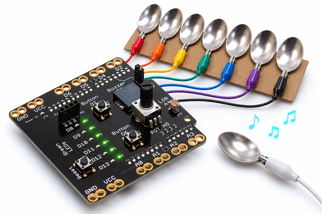
Build a seven-key spoon piano
Make foil keys into digital switches, play a scale and bend the pitch with the onboard dial.
Step 1 — Predict a touch-operated instrument
A grounded metal spoon will act as a movable switch. Touching a foil key connects its input to ground, and the buzzer plays that key’s note. Lift the spoon to stop.
You will build seven separated keys, use internal pull-up resistors to define untouched inputs, and turn the dial to bend pitch. Gather cardboard, seven foil or copper-tape strips, tape, a metal spoon and eight insulated clip leads.
Before you begin
Build and test one grounded contact before seven. INPUT_PULLUP means untouched HIGH, contact with ground LOW. Array index -1 is a sentinel, not a valid key.
Your goal: Scan inputs and resolve competing events. Show this with a prediction, a tested change and an explanation using the program’s names.
Retrieve one idea: what input, state or output did you change in the previous project?
Need a reminder? Build a pedestrian crossing.
Step 2 — Choose seven free inputs
Use A0, A1, A2, A3, D2, D4 and D5, in that order. Analog-labelled pins A0–A3 also work as digital inputs on the Uno.
This version deliberately uses seven keys. D6 is omitted because this shield also connects it to a button circuit with a pull-down; it is not a free input for the pull-up arrangement used here. A4 remains the onboard light sensor and A5 is the dial.
Disconnect USB and remove the traffic-light module or any external LED wiring before building, because D4 and D5 are needed as inputs now.
Step 3 — Prepare the key bed
Cut seven foil strips about 2 by 5 centimetres. Tape them in a row on cardboard with clear gaps, so neither the foil nor clip jaws can bridge neighbouring keys. Label the positions C, D, E, F, G, A and B.
These are low-voltage switch contacts. Keep them away from the shield’s VCC pads; they will be connected only to the listed input pads and the grounded spoon.
Step 4 — Connect key 1 to A0
Use one signal-coloured clip lead to connect the C foil key to the shield’s A0 edge pad. Keep this clip clear of adjacent foil, clips and pads.
Step 5 — Connect key 2 to A1
Use one signal-coloured clip lead to connect the D foil key to the shield’s A1 edge pad. Keep this clip clear of adjacent foil, clips and pads.
Step 6 — Connect key 3 to A2
Use one signal-coloured clip lead to connect the E foil key to the shield’s A2 edge pad. Keep this clip clear of adjacent foil, clips and pads.
Step 7 — Connect key 4 to A3
Use one signal-coloured clip lead to connect the F foil key to the shield’s A3 edge pad. Keep this clip clear of adjacent foil, clips and pads.
Step 8 — Connect key 5 to D2
Use one signal-coloured clip lead to connect the G foil key to the shield’s D2 edge pad. Keep this clip clear of adjacent foil, clips and pads.
Step 9 — Connect key 6 to D4
Use one signal-coloured clip lead to connect the A foil key to the shield’s D4 edge pad. Keep this clip clear of adjacent foil, clips and pads.
Step 10 — Connect key 7 to D5
Use one signal-coloured clip lead to connect the B foil key to the shield’s D5 edge pad. Keep this clip clear of adjacent foil, clips and pads.
Step 11 — Connect the spoon to ground
Use the black lead to connect the metal spoon to a shield ground pad. This gives every key a return path when the spoon touches it. No wire goes to VCC.
Check all seven input connections, confirm the foil strips do not touch, and refit the buzzer jumper if necessary. Reconnect USB.
Step 12 — Program the shield
Choose Arduino Uno, then Verify and Upload the supplied sketch. The English instructions describe the same behaviour as the C++ beside them. Keep the USB cable connected while you test.
Step 13 — Play a scale and bend a note
Begin with the dial near its midpoint. Touch C through B one at a time with the spoon. Each contact should sound one note and releasing it should stop the sound.
Hold the spoon on one key and turn the dial. The pitch shifts up or down by up to about 80 hertz. This is pitch bending, not a wah-wah filter. The serial console at 9600 baud shows the selected key and frequency.
Step 14 — Explain why touched means low
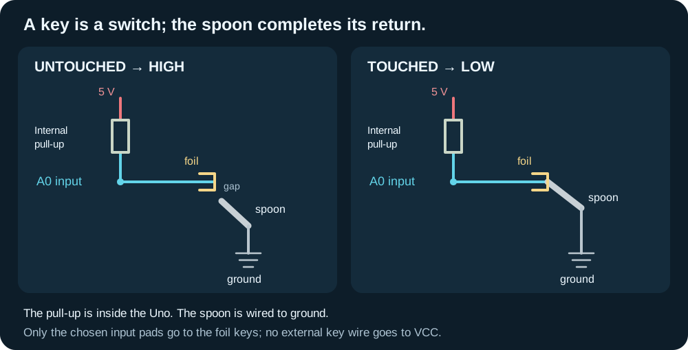
INPUT_PULLUP gives each untouched key a weak internal connection to the high level. The grounded spoon completes a stronger path to ground, so a touched key reads LOW. This is intentionally the opposite of the onboard D7 button’s active-high circuit.
The key and note arrays are paired. The program scans them in order and plays the first touched key, because this buzzer can play one tone at a time. Bridging two keys therefore does not create a chord.
Read this part of the actual starter
void loop() {
  int selected = -1;
  for (byte i = 0; i < KEY_COUNT; ++i) {
    if (digitalRead(KEY_PINS[i]) == LOW) {
      selected = i;
      break;
    }
  }
  const int bend = map(analogRead(POT_PIN), 0, 1023, -80, 80);
  const int frequency = selected < 0 ? 0 : static_cast<int>(NOTES[selected]) + bend;
  if (frequency != playingHz) {
    if (frequency == 0) noTone(BUZZER_PIN);
    else tone(BUZZER_PIN, frequency);
    playingHz = frequency;
These external keys use INPUT_PULLUP, so contact with ground reads LOW. The scan stores the first pressed index then breaks. -1 means none. The frequency expression checks selected before indexing NOTES; this avoids reading NOTES[-1].
Work through one case
If keys 1 and 3 are pressed together, index 0 wins because it is found first. With no key selected frequency is zero and noTone stops sound.
Your turn: complete the trace
With no key selected, selected=-1 and frequency=___. With keys at indices 2 and 5 both LOW, selected=___.
Compare your trace after trying
0, then 2. The first matching key wins because break ends the scan.
If your answer differs
Trace the condition before evaluating the selected branch.
Step 15 — Change the instrument and check it
Set the pitch-bend limits to 0 and 0 to keep standard notes regardless of dial position. Next restore the bend range and replace one entry in NOTES with 523 for a higher C.
Explain the complete switch path from input, through foil and spoon, to ground.
- A note plays untouched: look for bridged foil or a clip touching ground; check that none of the keys uses D6.
- One key is silent: inspect its clip contact with both foil and the correct pad.
- All keys are silent: check the spoon’s ground lead and the buzzer jumper.
- The highest-priority key wins when two touch: expected behaviour of the first-match scan.
Run a controlled experiment
Predict two simultaneous keys, release both, then change the bend range. Explain how this external-key polarity differs from shield D7.
- Save a copy of the working starter. Reset the board so stored state begins from the declared values.
- Write the expected result before editing. Change only the named factor; keep wiring and other settings fixed.
- Edit the C++ in the editor, Verify, then Upload to the connected Uno. The starter simulation does not execute your edited C++.
- Repeat the same input sequence. Record input, expected output, observed output and an explanation. Use labelled serial values where the sketch provides them.
- If the result differs, inspect the relevant condition and pin before changing another factor. Restore and upload the saved starter to recover.
Core task: explain one changed case. Optional extension: choose a boundary or timing case and justify the extra test. Use a paper trace or annotated screenshot when physical manipulation is inaccessible; distinguish predictions from measurements.
Independent check — try before revealing
Why must selected<0 be checked before reading NOTES[selected]? How does this differ from shield D7?
Hint
Trace the condition before evaluating the selected branch.
Reasoning and feedback
It prevents an invalid negative array lookup. These external contacts are active-LOW with pull-ups; shield D7 is active-HIGH with its own bias circuit.
Touch the grounded probe to a spoon contact; do not attach anything to a person or mains. This is a contact keyboard, not a body-resistance sensor.
If your explanation missed a condition or stored value, add that column to your trace and try a new input. A working upload alone does not answer this check.
Step 16 — The knob bends a note after a key is chosen
The spoon piano maps A5 into bend, from −80 to +80 Hz, then adds that offset to the selected entry in NOTES[].
Choose Cutaway and turn Wiper load off to represent the shield’s A5 input, which draws very little current. Move Turn the shaft to 25%, 50% and 75%. Record wiper voltage and ADC reading, and follow the moving contact on the resistive track.
Predict and explain: At the same knob position, will all seven keys necessarily play the same pitch?
Check your explanation
No. Each key supplies its own base note; bend adds the same offset to whichever note is selected. Near the knob’s midpoint the offset is close to zero. With the illustrated 5 V reference and no wiper load, the three positions give about 1.25 V / 256, 2.50 V / 512 and 3.75 V / 767. A voltage is available at A5 even though almost no current enters that input.
Step 17 — The sounding part of the spoon piano
A touched key selects a note, the knob adds pitch bend, and frequency is sent to the D3 sounder.
Choose Cutaway and press Play animation. Compare 440 Hz and 880 Hz using Change the pitch; use Tone off to enable the optional sound. The visible bending is slowed and enlarged. Pause, then drag Inspect one cycle through rising, steady and falling voltage.
Predict and explain: If every key is released, why must the sketch call noTone() rather than merely stop reading the keys?
Check your explanation
The sketch must explicitly stop the previously running tone when frequency becomes zero. The buzzer has no knowledge of which key was released; it responds to the electrical drive it receives. Changing voltage bends the bonded ceramic and brass diaphragm. Charge moves onto and off the electrodes, reversing during discharge; it does not pass through the ceramic. Try Electron flow to see the opposite direction convention for the same electrical behaviour.
