

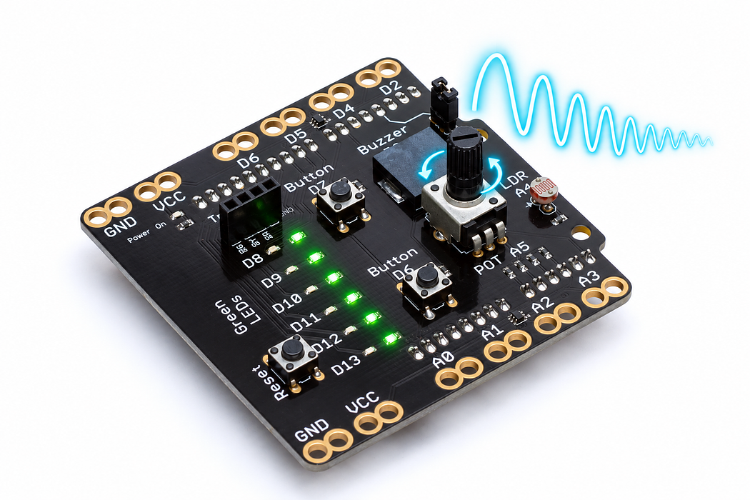
Turn the dial to bend a note
Use the potentiometer to choose a pitch, and the button to decide when the buzzer should sound.
Step 1 — Predict the effect of the dial
The dial will choose a frequency; D7 will act as the instrument’s gate. Turning the dial with the button released changes the selected pitch silently. Holding the button lets you hear it.
Predict the frequencies near the two ends of the dial and halfway between. You will connect an analog reading to a useful output range.
Before you begin
Know map and elapsed-time checks; retrieve level versus event.
Your goal: Update an output only when necessary. Show this with a prediction, a tested change and an explanation using the program’s names.
Retrieve one idea: what input, state or output did you change in the previous project?
Need a reminder? Give the shield a voice.
Step 2 — Find the control and the sounder
Use the onboard potentiometer at A5, button D7 and buzzer D3. Check the buzzer jumper with USB disconnected if it was removed in the previous activity. The light sensor at A4 is not used here.
Step 3 — Program the shield
Choose Arduino Uno, then Verify and Upload the supplied sketch. The English instructions describe the same behaviour as the C++ beside them. Keep the USB cable connected while you test.
Step 4 — Hear and measure the change
Open the serial console at 9600 baud. Turn the dial slowly and watch dial and frequency. Hold D7 to hear the changing pitch; release it to stop.
Record readings near the low end, midpoint and high end. The selected range is about 200 to 2000 hertz; near the midpoint it is about 1100 hertz. Real dial endpoints may fall slightly short of the nominal extremes.
Step 5 — Explain the chain from motion to sound
The potentiometer is a voltage divider. Its centre connection supplies a changing voltage to A5. The Uno converts that voltage into a whole-number reading; map then scales the number into a frequency.
The frequency is a software choice, not a voltage measurement. A tone at twice the frequency sounds an octave higher. Button D7 reads high when pressed, so it controls whether the selected tone is audible.
Read this part of the actual starter
void loop() {
  const int raw = analogRead(POT_PIN);
  const int selectedHz = map(raw, 0, 1023, 200, 2000);
  const bool pressed = digitalRead(BUTTON_PIN) == HIGH;
  if (pressed && selectedHz != playingHz) {
    tone(BUZZER_PIN, selectedHz);
    playingHz = selectedHz;
  } else if (!pressed && playingHz != 0) {
    noTone(BUZZER_PIN);
    playingHz = 0;
  }
  const unsigned long now = millis();
  if (now - lastReport >= 100) {
    lastReport = now;
selectedHz is recalculated from A5 each pass. Global playingHz remembers the command last sent to the buzzer. A changed selection while pressed calls tone; release calls noTone. Reporting is limited with elapsed time while input checks continue.
Work through one case
Raw 0 selects 200 Hz; 1023 selects 2000 Hz. If raw is unchanged while held, the tone command is not restarted. On release, playingHz becomes zero.
Your turn: complete the trace
Raw=0 and D7 held selects ___ Hz. Release calls ___ and sets playingHz to ___.
Compare your trace after trying
200 Hz; noTone; 0.
If your answer differs
Separate sound state from the timestamp used only for printing.
Step 6 — Change the instrument’s range
Change the mapping limits to 400 and 800. Predict the low, middle and high pitches before uploading. The same dial travel now covers a smaller frequency range, making fine adjustments easier.
Try making three named zones: below 341 plays 262 hertz, below 682 plays 330, and the remaining readings play 392. How does that feel different from a continuous sweep?
Run a controlled experiment
Use a 300–900 Hz range and test both endpoints plus release. Explain why changing the 100 ms report interval should not change how quickly the button is read.
- Save a copy of the working starter. Reset the board so stored state begins from the declared values.
- Write the expected result before editing. Change only the named factor; keep wiring and other settings fixed.
- Edit the C++ in the editor, Verify, then Upload to the connected Uno. The starter simulation does not execute your edited C++.
- Repeat the same input sequence. Record input, expected output, observed output and an explanation. Use labelled serial values where the sketch provides them.
- If the result differs, inspect the relevant condition and pin before changing another factor. Restore and upload the saved starter to recover.
Core task: explain one changed case. Optional extension: choose a boundary or timing case and justify the extra test. Use a paper trace or annotated screenshot when physical manipulation is inaccessible; distinguish predictions from measurements.
Step 7 — Check and troubleshoot
Explain why turning the dial still changes the printed frequency when the sound is off. Then demonstrate that releasing D7 always silences the buzzer.
- Values do not move: check that the code reads A5 rather than the neighbouring A4.
- Values move but there is no sound: hold D7, then check the D3 jumper.
- The pitch wobbles slightly at rest: small analog reading changes are normal; a narrower range or averaging can reduce their audible effect.
Independent check — try before revealing
Why does the code compare selectedHz with playingHz, and what happens if lastReport is reset on every loop?
Hint
Separate sound state from the timestamp used only for printing.
Reasoning and feedback
The comparison avoids restarting an unchanged tone. Resetting lastReport unconditionally stops the elapsed reporting interval from accumulating, so reports can disappear.
Selected frequency and currently playing frequency are different states. Serial throttling need not block control.
If your explanation missed a condition or stored value, add that column to your trace and try a new input. A working upload alone does not answer this check.
Step 8 — Inside the dial that chooses the note
A5 supplies raw, which becomes selectedHz through map(raw, 0, 1023, 200, 2000).
Choose Cutaway and turn Wiper load off to represent the shield’s A5 input, which draws very little current. Move Turn the shaft to 25%, 50% and 75%. Record wiper voltage and ADC reading, and follow the moving contact on the resistive track.
Predict and explain: At a fixed knob position, does releasing D7 change the voltage chosen by the wiper?
Check your explanation
No. The knob still selects the same voltage and frequency value. D7 separately controls whether tone() plays that selection. With the illustrated 5 V reference and no wiper load, the three positions give about 1.25 V / 256, 2.50 V / 512 and 3.75 V / 767. A voltage is available at A5 even though almost no current enters that input.
Step 9 — From selected frequency to a vibrating diaphragm
The pitch-changer sends selectedHz to D3 while D7 is held.
Choose Cutaway and press Play animation. Compare 440 Hz and 880 Hz using Change the pitch; use Tone off to enable the optional sound. The visible bending is slowed and enlarged. Pause, then drag Inspect one cycle through rising, steady and falling voltage.
Predict and explain: What changes when the selected frequency doubles: cycles each second, or the number of electrodes in the sounder?
Check your explanation
The voltage and mechanical vibration repeat more often each second, producing a higher pitch. The two electrodes and bonded diaphragm remain the same. Changing voltage bends the bonded ceramic and brass diaphragm. Charge moves onto and off the electrodes, reversing during discharge; it does not pass through the ceramic. Try Electron flow to see the opposite direction convention for the same electrical behaviour.
