

Your first blink
Make the shield respond, then explain the repeating sequence behind a blinking LED.
Step 1 — What you will discover
Make a visible output and distinguish setup, which runs once, from loop, which repeats.
Predict: How long does one complete on-and-off cycle take?
Before you begin
Find setup and loop; read milliseconds as thousandths of a second.
Your goal: Trace a repeating program. Show this with a prediction, a tested change and an explanation using the program’s names.
Retrieve one idea: what input, state or output did you change in the previous project?
Need a reminder? Meet your Crack the Code shield.
Step 2 — Meet this circuit
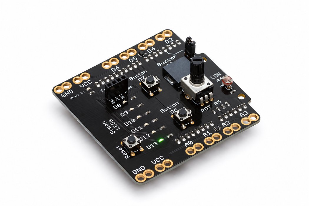
Use an Arduino Uno with the Crack the Code shield. The shield already connects its LEDs, knob, light sensor and buttons; this activity needs no jumper wires or breadboard.
If the shield is not fitted, disconnect USB power, align every shield pin with the Uno sockets, and press evenly without bending the pins. Reconnect the Uno with a USB data cable. Leave the traffic-light module disconnected for this activity.
Step 3 — Upload your program
Open the example below. Read the English plan, then choose Arduino C++ from the language selector and Arduino Uno from the board selector. Select Verify to compile. Select Pair board…, choose the Uno’s serial port, then select Upload. Use Chrome or Edge on a desktop computer with this HTTPS page for browser upload. If browser upload is unavailable, copy the complete C++ sketch into Arduino IDE, choose Arduino Uno and its port, and upload there.
Each upload replaces the previous program. Edit the supplied C++ when trying the challenges, then verify and upload again.
Step 4 — Read, edit and run
The English plan and complete Arduino sketch describe the same program. Keep one working copy before making changes.
Step 5 — Run it and collect evidence
Watch the shield LED beside D13 for ten seconds. It should be on for one second and off for one second. Count complete cycles, not every change. The Uno’s own D13 light may blink as well.
Step 6 — Explain what happened

pinMode prepares the output. digitalWrite changes its state. A thousand milliseconds is one second, so the two waits make a two-second cycle. setup() runs after power-up or reset; loop() repeats until the board is stopped or reprogrammed.
Statements such as delay(1000); end with a semicolon. Braces group the statements in a function. Text after // is a comment for people; changing it does not change the light.
Read this part of the actual starter
void loop() {
  digitalWrite(ledPin, HIGH);
  delay(1000);
  digitalWrite(ledPin, LOW);
  delay(1000);
}
const byte ledPin = 13; creates a fixed pin name. setup() runs once after reset and makes that pin an output. loop() repeats in order. HIGH and LOW set the output; delay pauses the sketch in milliseconds.
Work through one case
At 0 ms the LED turns on; at 1000 ms it turns off; at 2000 ms the next cycle starts. The period is 2 s and the frequency is 0.5 Hz, not 1 Hz.
Your turn: complete the trace
With 1000 ms on and 500 ms off, the period is ___ ms and the first off interval starts at ___ ms.
Compare your trace after trying
1500 ms; 1000 ms. The full period includes both waits.
If your answer differs
Mark successive rising edges rather than counting every change.
Step 7 — Change one thing
Change both waits to 250. Predict the number of complete cycles in ten seconds, upload, then count. Now change only the on-time to 100 and keep the off-time at 900.
Run a controlled experiment
Make a three-second cycle with the light on for one second. Draw the first two cycles before uploading, then compare your prediction with observation.
- Save a copy of the working starter. Reset the board so stored state begins from the declared values.
- Write the expected result before editing. Change only the named factor; keep wiring and other settings fixed.
- Edit the C++ in the editor, Verify, then Upload to the connected Uno. The starter simulation does not execute your edited C++.
- Repeat the same input sequence. Record input, expected output, observed output and an explanation. Use labelled serial values where the sketch provides them.
- If the result differs, inspect the relevant condition and pin before changing another factor. Restore and upload the saved starter to recover.
Core task: explain one changed case. Optional extension: choose a boundary or timing case and justify the extra test. Use a paper trace or annotated screenshot when physical manipulation is inaccessible; distinguish predictions from measurements.
Step 8 — Check your understanding
Explain why two waits are needed. If the light never seems to turn off, restore waits of 1000 before checking the hardware.
If nothing changes: check the power light, successful upload and the selected Uno port. Disconnect power before reseating a shield. Read the first compiler error before changing several lines at once.
Independent check — try before revealing
A learner changes both delays to 250 and calls it a 4 Hz blink. Diagnose the claim.
Hint
Mark successive rising edges rather than counting every change.
Reasoning and feedback
The full cycle is 500 ms, so frequency is 2 Hz. Four transitions per second are not four complete cycles.
One delay is only part of the period. Add the on and off durations. Changing a comment does not change execution.
If your explanation missed a condition or stored value, add that column to your trace and try a new input. A working upload alone does not answer this check.
Step 9 — Inside the light that blinks
Your sketch switches ledPin (D13) HIGH for 1000 ms and LOW for 1000 ms. This red, two-lead LED exposes the same light-emitting principle used by the shield’s indicators; their colour and package can differ.
Choose Cutaway and find the tiny chip, reflector cup and bond wire. Leave Reverse polarity off, set Supply voltage to 5 V, then press Play blink. Watch current and light switch together. Pause before changing the supply to 3 V and then 1 V; the explorer keeps a 220 Ω resistor in series.
Predict and explain: Does a LOW command leave the LED glowing, or stop the forward current? How would you recognise that in both the current display and the chip?
Check your explanation
A LOW command removes the forward drive in this circuit, so current and emitted light fall to approximately zero. The explorer blinks faster than this sketch at its default speed; select 0.5× to compare its one-second on and off intervals. The supply slider changes forward current during an on state. The lesson’s sketch separately determines which outputs are on and for how long.
