

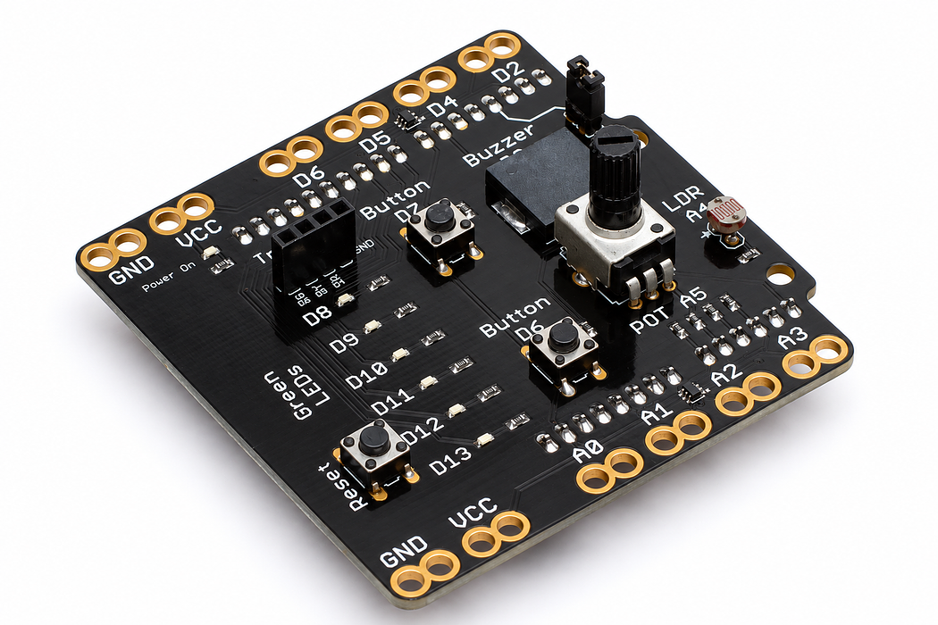
Meet your Crack the Code shield
Connect your shield, find its inputs and outputs, and learn how to run and change a program in the English IDE.
Step 1 — Your first learning goal
By the end, you will be able to identify an input, identify an output, connect the shield correctly, and upload a program. You need an Arduino Uno, the Crack the Code shield, a USB data cable and a computer. The traffic-light module comes later.
The shield already contains the connections and current-limiting resistors for its LEDs. Most lessons need no breadboard or extra wiring.
Before you begin
Read a labelled pin and distinguish a pin name from a reading.
Your goal: Identify the shield and verify the connections. Show this with a prediction, a tested change and an explanation using the program’s names.
Step 2 — Fit the shield
Disconnect USB before fitting or removing the shield. Align every pin with its Uno socket; check that neither row is shifted by one position. Press evenly. If it resists, lift it and inspect the alignment.
Loading assembly…
Disconnect U S B power. Align every shield pin with its matching Uno socket. Check both rows before pressing the shield down evenly.
Step 3 — Explore the board
Press Play for a guided tour. Each callout points to the part being explained: the six LEDs, knob, light sensor, both buttons, buzzer and mute jumper, traffic-light socket, and reset. Pause or drag to inspect any part.
The D6 button shares the traffic light’s green channel. Do not press it while that channel is configured as an output.
Loading assembly…
These six green L E Ds are outputs. Your program can light them individually to show a pattern, a count, or a result. The knob is an input. Turning it changes the reading on analog pin five, so your program can respond to its position. The light sensor measures changes in brightness on analog pin four. Cover it to give your program a different reading. The button on digital pin seven tells your program when you press or release it. The second button uses digital pin six. This pin is shared with the traffic light’s green channel, so do not press this button while driving that light. The buzzer is an output for notes, beeps, and alerts. Removing this jumper silences the buzzer without changing your program. This socket connects the traffic light. With power disconnected, match its ground, red, yellow, and green labels. Reset restarts your program from the beginning. It does not erase your code.
Step 4 — Follow a signal

Power and ground pass through the underside headers. A signal pin is a separate connection: it tells the program what happened, or tells an output what to do. The label GND means ground; VCC on this shield is the five-volt supply.
Step 5 — Connect and open the editor
Check the alignment once more, then connect the Uno to your computer with the USB data cable. Open Your first blink. Its editor includes an English plan and the complete Arduino program.
Read the plan, inspect the C++ tab, then use Verify and Upload. Select Arduino Uno and choose the connected device when prompted. Browser upload needs a supported desktop browser on HTTPS or localhost. If your browser does not offer the device, use the complete C++ sketch in Arduino IDE with Arduino Uno and the correct port selected.
Step 6 — Read the shape of a program
setup() runs once when the board starts or resets. It prepares pins and communication. loop() repeats the instructions that make the project respond. Braces group instructions; semicolons finish most statements. Comments explain a line to a person without changing what the board does.
Uploading replaces the program on the Uno. Changing the English text does not by itself change the uploaded program: generate or edit the C++ version, verify it, and upload again.
Read this part of the actual starter
void loop() {
  const unsigned long elapsed=millis()-started;
  ledMask=0;
  if (elapsed<6000) {
    const byte index=(elapsed/500)%6;
    for (byte i=0;i<6;++i) {
      const bool lit=i==index; digitalWrite(leds[i],lit);
      if(lit) ledMask |= (1 << i);
    }
  } else {
    const int count=map(analogRead(A5),0,1023,0,6);
    for (byte i=0;i<6;++i) {
      const bool lit=i<count; digitalWrite(leds[i],lit);
      if(lit) ledMask |= (1 << i);
Treat the acceptance sketch as a diagnostic tool. Its arrays and bit masks are support code that we revisit later. A5 is the knob, A4 the light sensor, D7 the active-HIGH button, D3 the buzzer and D8–D13 the LEDs. Pin names identify connections; they are not measured values.
Work through one case
The first six seconds chase the LEDs. Afterwards, turning A5 changes how many are lit. A line containing A5:512 describes a reading, not pin 512.
Your turn: complete the trace
The report shows A5:512 and D7:0. Which is a changing measurement and which names the connection?
Compare your trace after trying
A5 names the knob connection; 512 is its current sample. D7 names the button connection; 0 is its released reading.
If your answer differs
Change one physical control at a time and match its label to the report.
Step 7 — A habit for every lesson
- Predict: say what should happen before uploading.
- Run: observe the actual light, sound or reading.
- Explain: connect that observation to one instruction.
- Change: edit one value and predict the difference.
- Check: keep the working version and record what you learned.
For a shared classroom, one person can operate while another predicts and records; swap roles at the next activity. Use the LED-based lessons if sound is unsuitable, and remove the buzzer jumper with power disconnected to silence it.
Run a controlled experiment
Label an input–process–output diagram from your own board. Record one observed value for each input, including released and pressed D7. Explain one fault you could detect with this sketch.
- Save a copy of the working starter. Reset the board so stored state begins from the declared values.
- Write the expected result before editing. Change only the named factor; keep wiring and other settings fixed.
- Edit the C++ in the editor, Verify, then Upload to the connected Uno. The starter simulation does not execute your edited C++.
- Repeat the same input sequence. Record input, expected output, observed output and an explanation. Use labelled serial values where the sketch provides them.
- If the result differs, inspect the relevant condition and pin before changing another factor. Restore and upload the saved starter to recover.
Core task: explain one changed case. Optional extension: choose a boundary or timing case and justify the extra test. Use a paper trace or annotated screenshot when physical manipulation is inaccessible; distinguish predictions from measurements.
Step 8 — If the board does not respond
- No device appears: try a known USB data cable and another USB socket. A charge-only cable cannot upload.
- Upload fails: close other apps using the same serial port, confirm Uno and the correct device, and retry.
- The wrong result appears: confirm that you uploaded the current lesson, not an earlier sketch.
- Nothing lights: disconnect power and check that every shield pin is seated in the matching socket.
Ready to continue? Point to one input and one output, then explain which part of a program runs repeatedly.
Independent check — try before revealing
D7 stays 0 when you turn the knob. Is the button necessarily broken?
Hint
Change one physical control at a time and match its label to the report.
Reasoning and feedback
No. Turning the knob changes A5. Press and release D7 deliberately, then compare its readings. Test the input you are diagnosing.
Disconnect the traffic-light module for this check. D6 must be an input here. A simulation shows the model; it cannot certify the physical wiring.
If your explanation missed a condition or stored value, add that column to your trace and try a new input. A working upload alone does not answer this check.
Step 9 — Mirror your real shield
Want the model to follow your hands? Upload the live-monitor program below, then choose Live hardware in the shield controls and connect your Uno. Turn the knob, shade the light sensor or press either button: the page follows the readings sent by your board, including which LEDs are actually on.
This program replaces the previous sketch. Leave the traffic-light module disconnected while both buttons are inputs. After a short LED check and beep, the knob controls a light bar. Return to Simulation to explore without a connected board.
USB access requires HTTPS or localhost and a browser that supports Web Serial. Use the published guide or open the local site through localhost; a plain LAN address cannot request a USB serial port. If readings stop, the viewer marks them stale instead of presenting an old value as live.
Step 10 — Upload the live-monitor program
Choose Arduino C++, select Arduino Uno, Verify, then Pair board… and Upload. The sketch reports at 9600 baud. Disconnect other serial-monitor apps before connecting the live viewer.
Step 11 — Look inside the knob
Open the potentiometer with the cutaway slider. Turn the shaft and follow the moving wiper. The outer pins connect to ground and five volts; the middle pin takes its voltage from the contact point.
Start with Wiper load switched off to match the shield’s A5 input. At halfway, expect about 2.5 volts and ADC 512. Turn Wiper load on to add an output resistor to ground. Electron flow through the middle pin now changes with the knob, and the load also changes the output voltage: halfway gives 2.0 volts for the illustrated equal-resistance load.
