

Build an automatic night light
Calibrate a light sensor and prevent flickering with two switching thresholds.
Step 1 — What you will discover
Turn measurements into a decision and use a gap between switching thresholds to avoid rapid flickering.
Predict: If the light is on at level 30, what happens when the level rises to 50?
Before you begin
Know calibration, map and persistent Boolean state.
Your goal: Use calibration and hysteresis. Show this with a prediction, a tested change and an explanation using the program’s names.
Retrieve one idea: what input, state or output did you change in the previous project?
Need a reminder? Measure changing light.
Step 2 — Meet this circuit
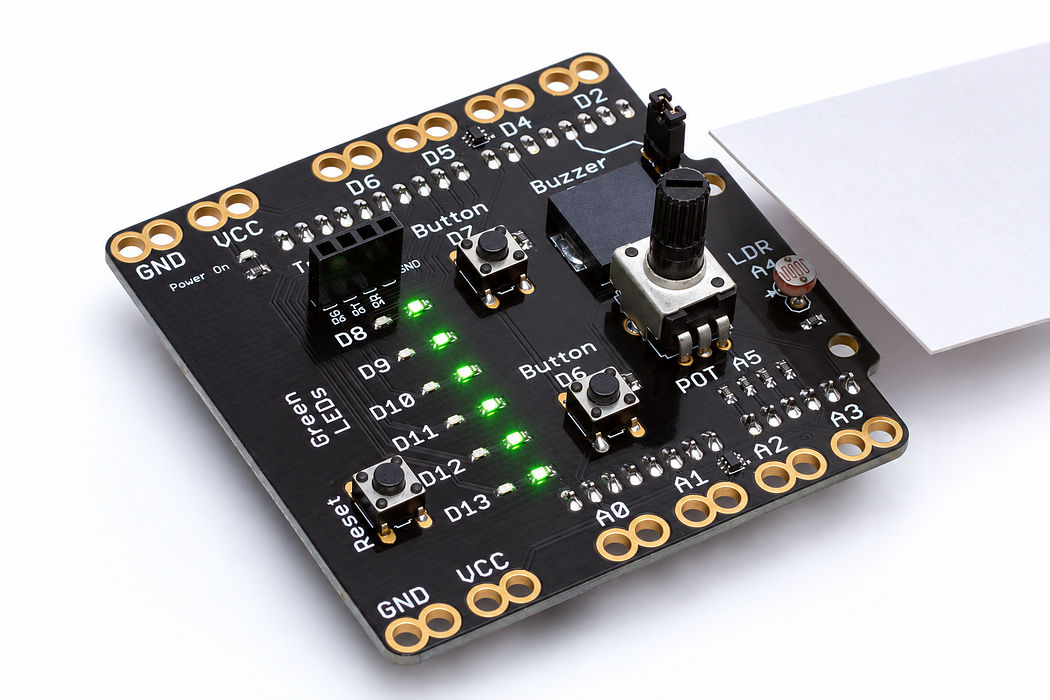
Use an Arduino Uno with the Crack the Code shield. The shield already connects its LEDs, knob, light sensor and buttons; this activity needs no jumper wires or breadboard.
If the shield is not fitted, disconnect USB power, align every shield pin with the Uno sockets, and press evenly without bending the pins. Reconnect the Uno with a USB data cable. Leave the traffic-light module disconnected for this activity.
Step 3 — Upload your program
Open the example below. Read the English plan, then choose Arduino C++ from the language selector and Arduino Uno from the board selector. Select Verify to compile. Select Pair board…, choose the Uno’s serial port, then select Upload. Use Chrome or Edge on a desktop computer with this HTTPS page for browser upload. If browser upload is unavailable, copy the complete C++ sketch into Arduino IDE, choose Arduino Uno and its port, and upload there.
Each upload replaces the previous program. Edit the supplied C++ when trying the challenges, then verify and upload again.
After upload, select Open Serial Monitor and set 9600 baud. Close other serial programs first so only one application owns the port. The Plot tab can display the labelled numeric readings.
Step 4 — Read, edit and run
The English plan and complete Arduino sketch describe the same program. Keep one working copy before making changes.
Step 5 — Run it and collect evidence
Before upload, replace darkReading and brightReading with the two readings you measured in the previous lesson. The supplied 150 and 800 are starting examples, not your calibration. Cover the sensor: D10 should turn on. Uncover it into your bright condition: it should turn off.
Step 6 — Explain what happened
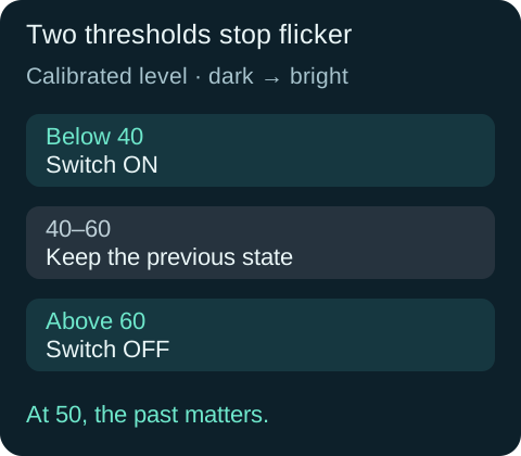
Mapping turns your measured dark endpoint into 0 and your bright endpoint into 100. Clamping keeps readings outside those endpoints within the display range. This is a relative scale for your test conditions, not a calibrated light percentage.
The light switches on below 40 and off above 60. Between those values it remembers its state. This gap is called hysteresis; it prevents small changes around one boundary repeatedly switching the light. The two input endpoints can be in either numerical order, but must differ.
Read this part of the actual starter
void loop() {
  int reading = analogRead(lightPin);
  if (darkReading == brightReading) {
    digitalWrite(ledPin, LOW);
    Serial.println("Choose two different calibration readings.");
    delay(500);
    return;
  }
  int level = constrain(map(reading, darkReading, brightReading, 0, 100), 0, 100);
  if (level < 40) lightOn = true;
  else if (level > 60) lightOn = false;
  digitalWrite(ledPin, lightOn ? HIGH : LOW);
  Serial.print("raw:"); Serial.print(reading);
  Serial.print(",level:"); Serial.print(level);
map converts your two calibration readings into relative percent, then constrain bounds it to 0–100. Below 40 the lamp turns on; above 60 it turns off. Between these boundaries global lightOn keeps its previous value. Equal calibration values are rejected to avoid division by zero.
Work through one case
With endpoints 150 and 800, raw 475 gives 50%. If previously on it stays on; if previously off it stays off. This gap prevents rapid switching near one threshold.
Your turn: complete the trace
Starting off, levels 30, 50, 70, 50 make the lamp on, ___, ___, ___.
Compare your trace after trying
on, off, off. The middle band keeps the previous state.
If your answer differs
Read < and > carefully; they do not include equality.
Step 7 — Change one thing
Approach the boundary slowly from dark, then from bright, and record the switching levels. Compare thresholds of 45/55 with 25/75. Which tolerates more small changes?
Run a controlled experiment
Calibrate in your room, test both approaches to the middle region, then justify different thresholds for a model cupboard light.
- Save a copy of the working starter. Reset the board so stored state begins from the declared values.
- Write the expected result before editing. Change only the named factor; keep wiring and other settings fixed.
- Edit the C++ in the editor, Verify, then Upload to the connected Uno. The starter simulation does not execute your edited C++.
- Repeat the same input sequence. Record input, expected output, observed output and an explanation. Use labelled serial values where the sketch provides them.
- If the result differs, inspect the relevant condition and pin before changing another factor. Restore and upload the saved starter to recover.
Core task: explain one changed case. Optional extension: choose a boundary or timing case and justify the extra test. Use a paper trace or annotated screenshot when physical manipulation is inaccessible; distinguish predictions from measurements.
Step 8 — Check your understanding
If the light stays on or off, read raw and level before changing the output code. Check calibration endpoints, sensor exposure and D10. Explain why the same level of 50 can produce either state depending on what happened earlier.
If nothing changes: check the power light, successful upload and the selected Uno port. Disconnect power before reseating a shield. Read the first compiler error before changing several lines at once.
Independent check — try before revealing
At exactly 40 and exactly 60, does the program assign a new lamp state?
Hint
Read < and > carefully; they do not include equality.
Reasoning and feedback
No. The tests are strictly less than 40 and greater than 60. At either exact boundary it retains its previous state.
Relative percent is not lux. Reversing the measured endpoints is supported; inventing endpoints without measuring is not calibration.
If your explanation missed a condition or stored value, add that column to your trace and try a new input. A working upload alone does not answer this check.
Step 9 — Separate the light sensor from the night-light decision
The sketch reads A4, converts it into calibrated level, and stores the lamp state in lightOn.
Open Cutaway, leave Power on, and compare Change the light at 25% and 75%. Record relative resistance and current. Find the two metal electrodes and the light-sensitive material between them; current crosses those gaps.
Predict and explain: Can the LDR itself remember whether the lamp was previously on when the light returns to the middle band?
Check your explanation
The cell changes resistance with illumination. The remembered state comes from lightOn and the program’s two thresholds: below 40 turns on, above 60 turns off, and the middle band preserves the previous state. More light lowers the cell’s resistance. At the same applied voltage this allows more current. On the shield, the LDR forms a voltage divider read at A4; use your recorded dark and bright readings to establish the ADC direction and range. The percentages here describe relative illumination and current, not lux or the sketch’s calibrated light level.
Step 10 — See what the lamp command does
The night-light program drives D10 HIGH or LOW according to lightOn. This red, two-lead LED exposes the same light-emitting principle used by the shield’s indicators; their colour and package can differ.
Choose Cutaway and find the tiny chip, reflector cup and bond wire. Leave Reverse polarity off, set Supply voltage to 5 V, then press Play blink. Watch current and light switch together. Pause before changing the supply to 3 V and then 1 V; the explorer keeps a 220 Ω resistor in series.
Predict and explain: Is the falling light level directly powering the lamp, or is the Arduino deciding when to drive it?
Check your explanation
The LDR supplies a changing input to the controller. The program then drives the LED output; the sensor and lamp are separate circuit functions. In this sketch the lamp is switched fully on or off rather than continuously dimmed. The supply slider changes forward current during an on state. The lesson’s sketch separately determines which outputs are on and for how long.
