

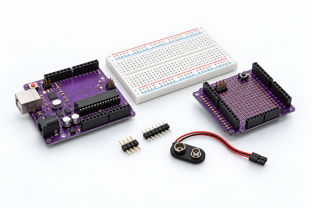
Use the shield, headers and workbench accessories
Blink the Uno built-in LED after inspecting the kit accessories. The battery snap remains disconnected.
Blink the Uno built-in LED after inspecting the kit accessories. The battery snap remains disconnected.
Use the Uno R3 Learning Kit. Build with power disconnected, check the labelled connections, then upload the supplied sketch. Drag or zoom the 3D model to inspect it from any angle.
Identify your part
The catalogue does not specify the protoshield revision or battery-lead termination. This is an identification and handling lesson, not an instruction to connect an unknown shield or 9V lead blindly.
Step 1 — Watch the complete build
Press Play for the narrated build. You can rotate and zoom the model while it plays, or follow the individual steps below.
Loading assembly…
Keep U S B disconnected while you build. On this breadboard, each group of five holes shares a connection; the centre channel separates the two halves. You can drag the 3D view to look around. Sort resistors, L E Ds and semiconductor packages into separate compartments. Keep their markings visible; transistors with the same case can have different pin orders. Add the Uno R3 prototyping shield. Keep its terminals accessible for the connections that follow. Add the Mini breadboard · 170 contacts. Keep its terminals accessible for the connections that follow. Add the 40-pin breakaway header · 2.54 millimetres. Keep its terminals accessible for the connections that follow. Add the Jumper wire · female / female. Keep its terminals accessible for the connections that follow. The snap connector is for an additional 9 volts battery. Keep it disconnected during these U S B-powered lessons. Never connect 9 volts to the Uno 5 volts pin or breadboard 5 volts rail. Use a suitable separate supply for the direct current motor, stepper motor or a loaded servo. Check all wiring. Connect the square U S B-B plug to the Uno and the U S B-A plug to your computer. Use Verify and Upload in the code editor below.
Step 2 — Understand the breadboard
Keep USB disconnected while you build. On this breadboard, each group of five holes shares a connection; the centre channel separates the two halves. You can drag the 3D view to look around.
Loading assembly…
Keep U S B disconnected while you build. On this breadboard, each group of five holes shares a connection; the centre channel separates the two halves. You can drag the 3D view to look around.
Step 3 — Organise the small parts
Sort resistors, LEDs and semiconductor packages into separate compartments. Keep their markings visible; transistors with the same case can have different pin orders.
Loading assembly…
Sort resistors, L E Ds and semiconductor packages into separate compartments. Keep their markings visible; transistors with the same case can have different pin orders.
Step 4 — Place Uno R3 prototyping shield
Add the Uno R3 prototyping shield. Keep its terminals accessible for the connections that follow.
Loading assembly…
Add the Uno R3 prototyping shield. Keep its terminals accessible for the connections that follow.
Step 5 — Place Mini breadboard · 170 contacts
Add the Mini breadboard · 170 contacts. Keep its terminals accessible for the connections that follow.
Loading assembly…
Add the Mini breadboard · 170 contacts. Keep its terminals accessible for the connections that follow.
Step 6 — Place 40-pin breakaway header · 2.54 mm
Add the 40-pin breakaway header · 2.54 mm. Keep its terminals accessible for the connections that follow.
Loading assembly…
Add the 40-pin breakaway header · 2.54 millimetres. Keep its terminals accessible for the connections that follow.
Step 7 — Place Jumper wire · female / female
Add the Jumper wire · female / female. Keep its terminals accessible for the connections that follow.
Loading assembly…
Add the Jumper wire · female / female. Keep its terminals accessible for the connections that follow.
Step 8 — Identify the battery connector
The snap connector is for an additional 9V battery. Keep it disconnected during these USB-powered lessons. Never connect 9V to the Uno 5V pin or breadboard 5V rail. Use a suitable separate supply for the DC motor, stepper motor or a loaded servo.
Loading assembly…
The snap connector is for an additional 9 volts battery. Keep it disconnected during these U S B-powered lessons. Never connect 9 volts to the Uno 5 volts pin or breadboard 5 volts rail. Use a suitable separate supply for the direct current motor, stepper motor or a loaded servo.
Step 9 — Place USB-A to USB-B cable · Uno
Check all wiring. Connect the square USB-B plug to the Uno and the USB-A plug to your computer. Use Verify and Upload in the code editor below.
Loading assembly…
Check all wiring. Connect the square U S B-B plug to the Uno and the U S B-A plug to your computer. Use Verify and Upload in the code editor below.
Step 10 — Program your Uno
Choose Arduino Uno. Verify, pair the board and Upload this sketch. Keep USB connected. Blink the Uno built-in LED after inspecting the kit accessories. The battery snap remains disconnected.
Step 11 — Try it and troubleshoot
Unplug USB before fitting a shield. Match every header bank without bending or offsetting the pins. Use the mini breadboard for a small circuit, and retain the same five-hole-strip rule. Store unused parts by type.
If it does not work
Shield revisions, header gender and battery lead termination vary. A barrel-plug lead must match the Uno centre-positive input. Bare leads need a suitable connector; do not improvise loose powered connections.
Parts List
Required Parts (1)
Use the components named in this tutorial. A computer and any additional power supply are not included.
x1
$64.70
In stockProject Summary
1 part total
Unavailable items will be skipped
