

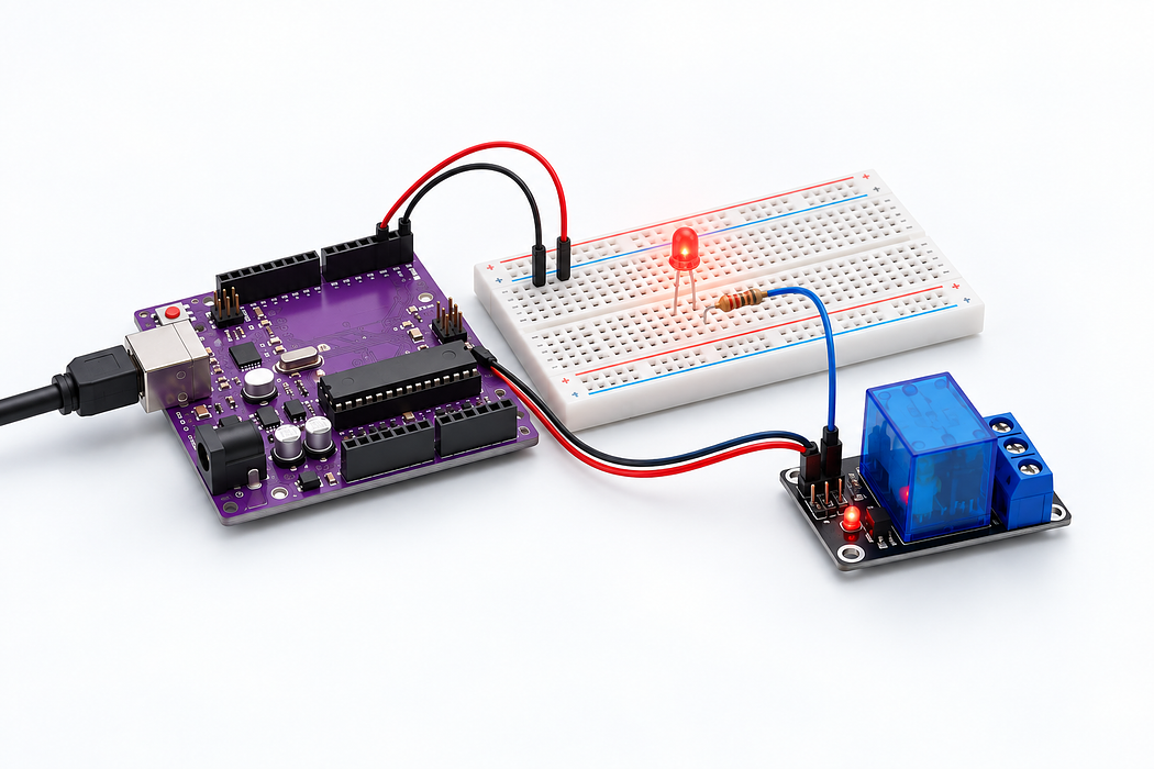
Switch a low-voltage LED with a relay
Toggle a relay module on D7 every 1.5 seconds. Its normally open contact switches a resistor-limited 5V LED. Set ACTIVE_LOW to match the supplied module.
Toggle a relay module on D7 every 1.5 seconds. Its normally open contact switches a resistor-limited 5V LED. Set ACTIVE_LOW to match the supplied module.
Use the Uno R3 Learning Kit. Build with power disconnected, check the labelled connections, then upload the supplied sketch. Drag or zoom the 3D model to inspect it from any angle.
Step 1 — Watch the complete build
Press Play for the narrated build. You can rotate and zoom the model while it plays, or follow the individual steps below.
Loading assembly…
Keep U S B disconnected while you build. On this breadboard, each group of five holes shares a connection; the centre channel separates the two halves. You can drag the 3D view to look around. Connect the Arduino’s five volt output to the positive rail. Connect Arduino ground to the ground rail. Add the Single-channel relay · contacts and control. Keep its terminals accessible for the connections that follow. Add the Red L E D · 5 millimetres. Its cathode lead goes into column 12 row E; the highlights show the remaining holes. Add the 330 ohms resistor. Its Pin 0 lead goes into column 18 row H; the highlights show the remaining holes. Connect the Single-channel relay · contacts and control’s supply pin to the positive rail. Connect the Single-channel relay · contacts and control’s ground pin to the ground rail. Connect the Single-channel relay · contacts and control’s IN pin to Arduino digital pin 7. Connect the relay's common switch contact to the positive rail. Connect the relay's normally open switch contact to one end of the resistor. Connect the other end of the resistor to the L E D’s anode lead. Connect the L E D’s cathode lead to the ground rail. Check all wiring. Connect the square U S B-B plug to the Uno and the U S B-A plug to your computer. Use Verify and Upload in the code editor below.
Step 2 — Understand the breadboard
Keep USB disconnected while you build. On this breadboard, each group of five holes shares a connection; the centre channel separates the two halves. You can drag the 3D view to look around.
Loading assembly…
Keep U S B disconnected while you build. On this breadboard, each group of five holes shares a connection; the centre channel separates the two halves. You can drag the 3D view to look around.
Step 3 — Connect Uno 5V → T+ rail 3
Connect the Arduino’s five volt output to the positive rail.
| Connect | To |
|---|---|
| Uno 5V | T+ rail 3 |
Loading assembly…
Connect the Arduino’s five volt output to the positive rail.
Step 4 — Connect Uno GND → T- rail 1
Connect Arduino ground to the ground rail.
| Connect | To |
|---|---|
| Uno GND | T- rail 1 |
Loading assembly…
Connect Arduino ground to the ground rail.
Step 5 — Place Single-channel relay · contacts and control
Add the Single-channel relay · contacts and control. Keep its terminals accessible for the connections that follow.
Loading assembly…
Add the Single-channel relay · contacts and control. Keep its terminals accessible for the connections that follow.
Step 6 — Place Red LED · 5 mm
Add the Red LED · 5 mm. Its cathode lead goes into column 12 row E; the highlights show the remaining holes.
Exact breadboard holes
- led · cathode → column 12 row E
- led · anode → column 13 row E
Loading assembly…
Add the Red L E D · 5 millimetres. Its cathode lead goes into column 12 row E; the highlights show the remaining holes.
Step 7 — Place 330 Ω resistor
Add the 330 Ω resistor. Its Pin 0 lead goes into column 18 row H; the highlights show the remaining holes.
Exact breadboard holes
- r · Pin 0 → column 18 row H
- r · Pin 1 → column 22 row H
Loading assembly…
Add the 330 ohms resistor. Its Pin 0 lead goes into column 18 row H; the highlights show the remaining holes.
Step 8 — Connect Single-channel relay · contacts and control VCC → T+ rail 29
Connect the Single-channel relay · contacts and control’s supply pin to the positive rail.
| Connect | To |
|---|---|
| Single-channel relay · contacts and control VCC | T+ rail 29 |
Loading assembly…
Connect the Single-channel relay · contacts and control’s supply pin to the positive rail.
Step 9 — Connect Single-channel relay · contacts and control GND → T- rail 29
Connect the Single-channel relay · contacts and control’s ground pin to the ground rail.
| Connect | To |
|---|---|
| Single-channel relay · contacts and control GND | T- rail 29 |
Loading assembly…
Connect the Single-channel relay · contacts and control’s ground pin to the ground rail.
Step 10 — Connect Single-channel relay · contacts and control IN → Uno D7
Connect the Single-channel relay · contacts and control’s IN pin to Arduino digital pin 7.
| Connect | To |
|---|---|
| Single-channel relay · contacts and control IN | Uno D7 |
Loading assembly…
Connect the Single-channel relay · contacts and control’s IN pin to Arduino digital pin 7.
Step 11 — Connect Single-channel relay · contacts and control COM → T+ rail 28
Connect the Single-channel relay · contacts and control’s COM pin to the positive rail.
| Connect | To |
|---|---|
| Single-channel relay · contacts and control COM | T+ rail 28 |
Loading assembly…
Connect the relay's common switch contact to the positive rail.
Step 12 — Connect Single-channel relay · contacts and control NO → column 18 row J
Connect the Single-channel relay · contacts and control’s NO pin to one end of the resistor.
| Connect | To |
|---|---|
| Single-channel relay · contacts and control NO | column 18 row J |
Loading assembly…
Connect the relay's normally open switch contact to one end of the resistor.
Step 13 — Connect column 22 row J → column 13 row A
Connect the other end of the resistor to the LED’s anode lead.
| Connect | To |
|---|---|
| column 22 row J | column 13 row A |
Loading assembly…
Connect the other end of the resistor to the L E D’s anode lead.
Step 14 — Connect column 12 row A → T- rail 11
Connect the LED’s cathode lead to the ground rail.
| Connect | To |
|---|---|
| column 12 row A | T- rail 11 |
Loading assembly…
Connect the L E D’s cathode lead to the ground rail.
Step 15 — Place USB-A to USB-B cable · Uno
Check all wiring. Connect the square USB-B plug to the Uno and the USB-A plug to your computer. Use Verify and Upload in the code editor below.
Loading assembly…
Check all wiring. Connect the square U S B-B plug to the Uno and the U S B-A plug to your computer. Use Verify and Upload in the code editor below.
Step 16 — Program your Uno
Choose Arduino Uno. Verify, pair the board and Upload this sketch. Keep USB connected. Toggle a relay module on D7 every 1.5 seconds. Its normally open contact switches a resistor-limited 5V LED. Set ACTIVE_LOW to match the supplied module.
Step 17 — Try it and troubleshoot
You hear the relay click and see the LED light. COM connects to NO only while energised. Check the printed contact labels rather than assuming terminal order.
If it does not work
This guide uses only low-voltage 5V wiring. Do not connect mains. A bare relay coil needs a transistor and flyback diode; this lesson expects the included driver module.
Parts List
Required Parts (1)
Use the components named in this tutorial. A computer and any additional power supply are not included.
x1
$64.70
In stockProject Summary
1 part total
Unavailable items will be skipped
