

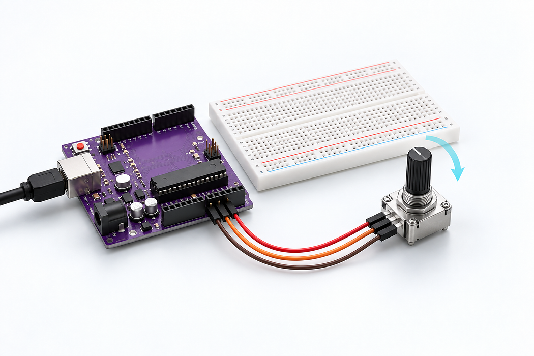
Read a rotary potentiometer
Read analog input A0 and print position from 0 to 1023 at 115200 baud. On this USB-powered Uno, ground is near 0 and the 5V supply is near 1023; a centred linear potentiometer gives roughly 512.
Turn a knob into a voltage the Arduino can read. Build a simple three-wire circuit, see why the breadboard holes connect, then compare the centre pin’s voltage with the Arduino’s numeric reading.
Use the Uno R3 Learning Kit. Build with power disconnected, check the labelled connections, then upload the supplied sketch. Drag or zoom the 3D model to inspect it from any angle.
Step 1 — Watch the complete build
Press Play for the narrated build. You can rotate and zoom the model while it plays, or follow the individual steps below.
Loading assembly…
This knob lets us choose a voltage for the Arduino to read. Fit the potentiometer in these three holes, with its terminals facing the Arduino. Each terminal goes in a separate numbered strip. The middle one is called the wiper; its voltage changes as we turn the knob. Connect this outer terminal to the Arduino’s five volt output with the red wire. Inside the breadboard, one metal strip joins these five holes. That’s why the jumper can use a free hole in the same numbered strip. The long power rails aren’t needed for this circuit. Connect the other outer terminal to Arduino ground with the black wire. Ground gives us the zero-volt reference for measuring the middle terminal. The red and black wires will supply the two ends when we connect U S B. Connect the middle terminal to analog input zero with the blue wire. The Arduino measures the voltage here as you turn the knob. Check the three wires, then connect the square U S B plug to the Arduino and the other end to your computer. That powers the circuit. To read your real knob, choose Arduino Uno and upload the supplied sketch. Keep U S B connected for the readings. Watch the centre pin as the knob turns: its voltage rises from zero to five volts. Halfway gives about two and a half volts. The Arduino turns that voltage into a number from zero to one thousand and twenty-three; halfway is about five hundred and twelve. Pause here and try the knob yourself.
Step 2 — Seat the potentiometer
This knob lets us choose a voltage for the Arduino to read. Fit the potentiometer in these three holes, with its terminals facing the Arduino. Each terminal goes in a separate numbered strip. The middle one is called the wiper; its voltage changes as we turn the knob.
Exact breadboard holes
- pot · 1 → column 12 row G
- pot · WIPER → column 13 row G
- pot · 3 → column 14 row G
Loading assembly…
This knob lets us choose a voltage for the Arduino to read. Fit the potentiometer in these three holes, with its terminals facing the Arduino. Each terminal goes in a separate numbered strip. The middle one is called the wiper; its voltage changes as we turn the knob.
Step 3 — Connect the 5V outer terminal
Connect this outer terminal to the Arduino’s five volt output with the red wire. Inside the breadboard, one metal strip joins these five holes. That’s why the jumper can use a free hole in the same numbered strip. The long power rails aren’t needed for this circuit.
| Connect | To |
|---|---|
| column 12 row J | Uno 5V |
Loading assembly…
Connect this outer terminal to the Arduino’s five volt output with the red wire. Inside the breadboard, one metal strip joins these five holes. That’s why the jumper can use a free hole in the same numbered strip. The long power rails aren’t needed for this circuit.
Step 4 — Connect the ground outer terminal
Connect the other outer terminal to Arduino ground with the black wire. Ground gives us the zero-volt reference for measuring the middle terminal. The red and black wires will supply the two ends when we connect USB.
| Connect | To |
|---|---|
| column 14 row J | Uno GND |
Loading assembly…
Connect the other outer terminal to Arduino ground with the black wire. Ground gives us the zero-volt reference for measuring the middle terminal. The red and black wires will supply the two ends when we connect U S B.
Step 5 — Connect the centre wiper to A0
Connect the middle terminal to analog input zero with the blue wire. The Arduino measures the voltage here as you turn the knob.
| Connect | To |
|---|---|
| column 13 row J | Uno A0 |
Loading assembly…
Connect the middle terminal to analog input zero with the blue wire. The Arduino measures the voltage here as you turn the knob.
Step 6 — Connect USB and upload
Check the three wires, then connect the square USB plug to the Arduino and the other end to your computer. That powers the circuit. To read your real knob, choose Arduino Uno and upload the supplied sketch. Keep USB connected for the readings.
Loading assembly…
Check the three wires, then connect the square U S B plug to the Arduino and the other end to your computer. That powers the circuit. To read your real knob, choose Arduino Uno and upload the supplied sketch. Keep U S B connected for the readings.
Step 7 — Turn the knob and read the voltage
Watch the centre pin as the knob turns: its voltage rises from zero to five volts. Halfway gives about two and a half volts. The Arduino turns that voltage into a number from zero to one thousand and twenty-three; halfway is about five hundred and twelve. Pause here and try the knob yourself.
Loading assembly…
Watch the centre pin as the knob turns: its voltage rises from zero to five volts. Halfway gives about two and a half volts. The Arduino turns that voltage into a number from zero to one thousand and twenty-three; halfway is about five hundred and twelve. Pause here and try the knob yourself.
Step 8 — Program your Uno
Choose Arduino Uno. Verify, pair the board and Upload this sketch. Keep USB connected. Read analog input A0 and print position from 0 to 1023 at 115200 baud. On this USB-powered Uno, ground is near 0 and the 5V supply is near 1023; a centred linear potentiometer gives roughly 512.
Step 9 — Explore the live readings
Before turning the knob to the middle, predict the reading. On your real circuit, upload the sketch and open the live plot: halfway should be about 512. Turn slowly to both ends, then hold the knob still and watch the trace settle. The 3D voltage display is a model; the live plot shows values sent by your connected Uno. For an extra experiment, disconnect USB and swap only the two outer wires. Reconnect and predict how the direction changes.
Step 10 — Troubleshooting
A reading stuck near 0 or 1023 can mean the blue wire is on an outer terminal’s strip instead of the centre strip. Check G12/J12 → 5V, G13/J13 → A0 and G14/J14 → ground. If the reading jumps with the knob untouched, check the middle connection and common ground. Small variations are normal. No live data? Select the correct Uno port, upload the sketch and use 115200 baud. Use the 5V socket, not VIN; disconnect USB before moving wires.
Parts List
Required Parts (1)
Use the components named in this tutorial. A computer and any additional power supply are not included.
x1
$64.70
In stockProject Summary
1 part total
Unavailable items will be skipped
