

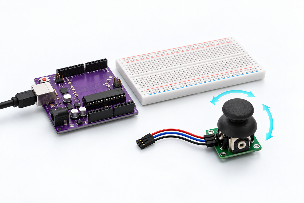
Read the joystick and its button
Read joystick X on A0 and Y on A1. Read its active-low push switch on D2. Print x, y and pressed values.
Read joystick X on A0 and Y on A1. Read its active-low push switch on D2. Print x, y and pressed values.
Use the Uno R3 Learning Kit. Build with power disconnected, check the labelled connections, then upload the supplied sketch. Drag or zoom the 3D model to inspect it from any angle.
Also needed
A module with male header pins needs female-to-male jumpers, or the supplied female-to-female leads joined to breadboard male jumpers.
Step 1 — Watch the complete build
Press Play for the narrated build. You can rotate and zoom the model while it plays, or follow the individual steps below.
Loading assembly…
Keep U S B disconnected while you build. On this breadboard, each group of five holes shares a connection; the centre channel separates the two halves. You can drag the 3D view to look around. Connect the Arduino’s five volt output to the positive rail. Connect Arduino ground to the ground rail. Place the joystick module beside the breadboard, turned 90 degrees so its header faces the wiring area. Use its printed ground, 5 volts, VRX, VRY and SW names to identify the header. Connect the LR0001 dual-axis XY joystick’s ground pin to the ground rail. Connect the LR0001 dual-axis XY joystick’s 5 volts pin to the positive rail. Connect the LR0001 dual-axis XY joystick’s VRX pin to Arduino analog input 0. Connect the LR0001 dual-axis XY joystick’s VRY pin to Arduino analog input 1. Connect the LR0001 dual-axis XY joystick’s SW pin to Arduino digital pin 2. Check all wiring. Connect the square U S B-B plug to the Uno and the U S B-A plug to your computer. Use Verify and Upload in the code editor below.
Step 2 — Understand the breadboard
Keep USB disconnected while you build. On this breadboard, each group of five holes shares a connection; the centre channel separates the two halves. You can drag the 3D view to look around.
Loading assembly…
Keep U S B disconnected while you build. On this breadboard, each group of five holes shares a connection; the centre channel separates the two halves. You can drag the 3D view to look around.
Step 3 — Connect Uno 5V → T+ rail 3
Connect the Arduino’s five volt output to the positive rail.
| Connect | To |
|---|---|
| Uno 5V | T+ rail 3 |
Loading assembly…
Connect the Arduino’s five volt output to the positive rail.
Step 4 — Connect Uno GND → T- rail 1
Connect Arduino ground to the ground rail.
| Connect | To |
|---|---|
| Uno GND | T- rail 1 |
Loading assembly…
Connect Arduino ground to the ground rail.
Step 5 — Place the joystick
Place the joystick module beside the breadboard, turned 90 degrees so its header faces the wiring area. Use its printed GND, 5V, VRX, VRY and SW names to identify the header.
Loading assembly…
Place the joystick module beside the breadboard, turned 90 degrees so its header faces the wiring area. Use its printed ground, 5 volts, VRX, VRY and SW names to identify the header.
Step 6 — Connect LR0001 dual-axis XY joystick GND → T- rail 15
Connect the LR0001 dual-axis XY joystick’s ground pin to the ground rail.
| Connect | To |
|---|---|
| LR0001 dual-axis XY joystick GND | T- rail 15 |
Loading assembly…
Connect the LR0001 dual-axis XY joystick’s ground pin to the ground rail.
Step 7 — Connect LR0001 dual-axis XY joystick 5V → T+ rail 16
Connect the LR0001 dual-axis XY joystick’s 5V pin to the positive rail.
| Connect | To |
|---|---|
| LR0001 dual-axis XY joystick 5V | T+ rail 16 |
Loading assembly…
Connect the LR0001 dual-axis XY joystick’s 5 volts pin to the positive rail.
Step 8 — Connect LR0001 dual-axis XY joystick VRX → Uno A0
Connect the LR0001 dual-axis XY joystick’s VRX pin to Arduino analog input 0.
| Connect | To |
|---|---|
| LR0001 dual-axis XY joystick VRX | Uno A0 |
Loading assembly…
Connect the LR0001 dual-axis XY joystick’s VRX pin to Arduino analog input 0.
Step 9 — Connect LR0001 dual-axis XY joystick VRY → Uno A1
Connect the LR0001 dual-axis XY joystick’s VRY pin to Arduino analog input 1.
| Connect | To |
|---|---|
| LR0001 dual-axis XY joystick VRY | Uno A1 |
Loading assembly…
Connect the LR0001 dual-axis XY joystick’s VRY pin to Arduino analog input 1.
Step 10 — Connect LR0001 dual-axis XY joystick SW → Uno D2
Connect the LR0001 dual-axis XY joystick’s SW pin to Arduino digital pin 2.
| Connect | To |
|---|---|
| LR0001 dual-axis XY joystick SW | Uno D2 |
Loading assembly…
Connect the LR0001 dual-axis XY joystick’s SW pin to Arduino digital pin 2.
Step 11 — Place USB-A to USB-B cable · Uno
Check all wiring. Connect the square USB-B plug to the Uno and the USB-A plug to your computer. Use Verify and Upload in the code editor below.
Loading assembly…
Check all wiring. Connect the square U S B-B plug to the Uno and the U S B-A plug to your computer. Use Verify and Upload in the code editor below.
Step 12 — Program your Uno
Choose Arduino Uno. Verify, pair the board and Upload this sketch. Keep USB connected. Read joystick X on A0 and Y on A1. Read its active-low push switch on D2. Print x, y and pressed values.
Step 13 — Explore the live readings
Move the stick through its range and press down. The centre is approximately half scale; use a small dead zone in a game controller.
Step 14 — Troubleshooting
Follow the module’s printed names. If the plot is fixed, check that the signal is not accidentally connected to a power pin.
Parts List
Required Parts (1)
Use the components named in this tutorial. A computer and any additional power supply are not included.
x1
$64.70
In stockProject Summary
1 part total
Unavailable items will be skipped
