

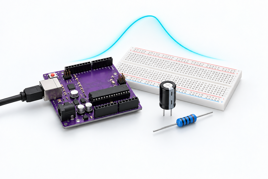
Watch a capacitor charge and discharge
Switch D8 every five seconds. Charge and discharge 10 microfarads through 100 kilohms and plot its A0 voltage.
Switch D8 every five seconds. Charge and discharge 10 microfarads through 100 kilohms and plot its A0 voltage.
Use the Uno R3 Learning Kit. Build with power disconnected, check the labelled connections, then upload the supplied sketch. Drag or zoom the 3D model to inspect it from any angle.
Step 1 — Watch the complete build
Press Play for the narrated build. You can rotate and zoom the model while it plays, or follow the individual steps below.
Loading assembly…
Keep U S B disconnected while you build. On this breadboard, each group of five holes shares a connection; the centre channel separates the two halves. You can drag the 3D view to look around. Connect Arduino ground to the ground rail. Add the 22 picofarads ceramic capacitor. Its 0 lead goes into column 3 row C; the highlights show the remaining holes. Add the 100 nanofarads ceramic capacitor. Its 0 lead goes into column 7 row C; the highlights show the remaining holes. Add the 100 microfarads electrolytic capacitor · 50 volts. Its - lead goes into column 24 row H; the highlights show the remaining holes. Add the 10 microfarads electrolytic capacitor · 50 volts. Its - lead goes into column 15 row E; the highlights show the remaining holes. Add the 100 kiloohms resistor. Its Pin 0 lead goes into column 8 row H; the highlights show the remaining holes. Connect Arduino digital pin 8 to one end of the resistor. Connect the other end of the resistor to the capacitor’s + pin. Connect the capacitor’s + pin to Arduino analog input 0. Connect the capacitor’s - pin to the ground rail. Check all wiring. Connect the square U S B-B plug to the Uno and the U S B-A plug to your computer. Use Verify and Upload in the code editor below.
Step 2 — Understand the breadboard
Keep USB disconnected while you build. On this breadboard, each group of five holes shares a connection; the centre channel separates the two halves. You can drag the 3D view to look around.
Loading assembly…
Keep U S B disconnected while you build. On this breadboard, each group of five holes shares a connection; the centre channel separates the two halves. You can drag the 3D view to look around.
Step 3 — Connect Uno GND → T- rail 1
Connect Arduino ground to the ground rail.
| Connect | To |
|---|---|
| Uno GND | T- rail 1 |
Loading assembly…
Connect Arduino ground to the ground rail.
Step 4 — Place 22 pF ceramic capacitor
Add the 22 pF ceramic capacitor. Its 0 lead goes into column 3 row C; the highlights show the remaining holes.
Exact breadboard holes
- small · 0 → column 3 row C
- small · 1 → column 4 row C
Loading assembly…
Add the 22 picofarads ceramic capacitor. Its 0 lead goes into column 3 row C; the highlights show the remaining holes.
Step 5 — Place 100 nF ceramic capacitor
Add the 100 nF ceramic capacitor. Its 0 lead goes into column 7 row C; the highlights show the remaining holes.
Exact breadboard holes
- bypass · 0 → column 7 row C
- bypass · 1 → column 8 row C
Loading assembly…
Add the 100 nanofarads ceramic capacitor. Its 0 lead goes into column 7 row C; the highlights show the remaining holes.
Step 6 — Place 100 µF electrolytic capacitor · 50 V
Add the 100 µF electrolytic capacitor · 50 V. Its - lead goes into column 24 row H; the highlights show the remaining holes.
Exact breadboard holes
- large · - → column 24 row H
- large · + → column 25 row H
Loading assembly…
Add the 100 microfarads electrolytic capacitor · 50 volts. Its - lead goes into column 24 row H; the highlights show the remaining holes.
Step 7 — Place 10 µF electrolytic capacitor · 50 V
Add the 10 µF electrolytic capacitor · 50 V. Its - lead goes into column 15 row E; the highlights show the remaining holes.
Exact breadboard holes
- cap · - → column 15 row E
- cap · + → column 16 row E
Loading assembly…
Add the 10 microfarads electrolytic capacitor · 50 volts. Its - lead goes into column 15 row E; the highlights show the remaining holes.
Step 8 — Place 100 kΩ resistor
Add the 100 kΩ resistor. Its Pin 0 lead goes into column 8 row H; the highlights show the remaining holes.
Exact breadboard holes
- r · Pin 0 → column 8 row H
- r · Pin 1 → column 12 row H
Loading assembly…
Add the 100 kiloohms resistor. Its Pin 0 lead goes into column 8 row H; the highlights show the remaining holes.
Step 9 — Connect Uno D8 → column 8 row J
Connect Arduino digital pin 8 to one end of the resistor.
| Connect | To |
|---|---|
| Uno D8 | column 8 row J |
Loading assembly…
Connect Arduino digital pin 8 to one end of the resistor.
Step 10 — Connect column 12 row J → column 16 row A
Connect the other end of the resistor to the capacitor’s + pin.
| Connect | To |
|---|---|
| column 12 row J | column 16 row A |
Loading assembly…
Connect the other end of the resistor to the capacitor’s + pin.
Step 11 — Connect column 16 row B → Uno A0
Connect the capacitor’s + pin to Arduino analog input 0.
| Connect | To |
|---|---|
| column 16 row B | Uno A0 |
Loading assembly…
Connect the capacitor’s + pin to Arduino analog input 0.
Step 12 — Connect column 15 row A → T- rail 15
Connect the capacitor’s - pin to the ground rail.
| Connect | To |
|---|---|
| column 15 row A | T- rail 15 |
Loading assembly…
Connect the capacitor’s - pin to the ground rail.
Step 13 — Place USB-A to USB-B cable · Uno
Check all wiring. Connect the square USB-B plug to the Uno and the USB-A plug to your computer. Use Verify and Upload in the code editor below.
Loading assembly…
Check all wiring. Connect the square U S B-B plug to the Uno and the U S B-A plug to your computer. Use Verify and Upload in the code editor below.
Step 14 — Program your Uno
Choose Arduino Uno. Verify, pair the board and Upload this sketch. Keep USB connected. Switch D8 every five seconds. Charge and discharge 10 microfarads through 100 kilohms and plot its A0 voltage.
Step 15 — Explore the live readings
The curve rises and falls smoothly, with a time constant near one second. Disconnect USB, wait for discharge through the resistor, and substitute 100 microfarads: the response is about ten times slower. The 100nF part is useful beside IC power pins. A 22pF capacitor is for much faster circuits; this sampling loop cannot resolve its RC curve.
Step 16 — Troubleshooting
Check the electrolytic stripe is at ground. A reading stuck at an endpoint usually means the resistor was bypassed by a shared breadboard strip. The three comparison capacitors occupy separate, unused columns; do not jumper them into the active circuit.
Parts List
Required Parts (1)
Use the components named in this tutorial. A computer and any additional power supply are not included.
x1
$64.70
In stockProject Summary
1 part total
Unavailable items will be skipped
