

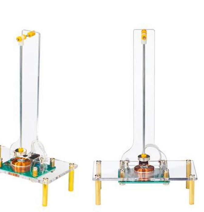
Soldering the DIY Electromagnetic Swing Kit
Build the TJ-56-678 electromagnetic swing — a self-driving pendulum that a Hall sensor and a 1000-turn coil keep swinging forever. A complete through-hole soldering project with 18 illustrated assembly steps.
The Electronic Swing (kit code TJ-56-678) is a pendulum that pushes itself. A 12 mm magnet hangs from a rod on a low-friction pivot. Every time it passes over a Hall-effect sensor, the circuit fires a 1000-turn coil for a fraction of a second and shoves the magnet away again. Give it a nudge and it keeps swinging for as long as it has power.
It is an excellent learn-to-solder project: every component is through-hole, there are only a dozen or so parts on the board, and the finished result actually does something. Along the way you meet the Hall effect, an inductor storing and releasing energy, a flyback diode, and a two-transistor switch.
How the circuit works
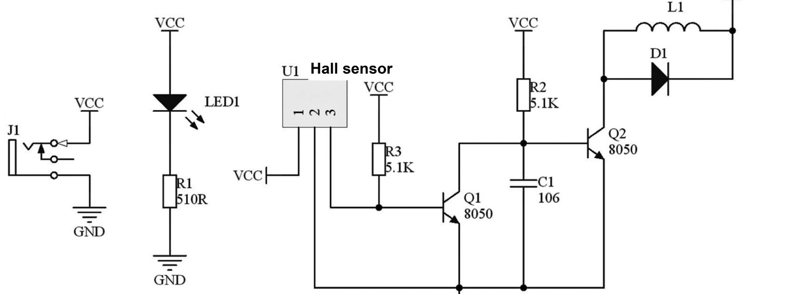
The 3144 is a magnetic sensor built around the Hall effect. When the magnet swings over it, the sensor detects the field and pulls its output low. That turns Q1 off, which in turn switches Q2 on.
With Q2 conducting, current flows through the coil L1 and generates a magnetic field. Which way that field points is set by the direction the current runs around the winding — the right-hand rule. The coil is wired so its field repels the magnet, and the magnet gets pushed away.
As soon as the magnet has moved clear, the Hall sensor stops seeing a field, its output goes high, Q1 turns back on and Q2 switches off. The energy still stored in the coil is dumped safely through the flyback diode D1 rather than punching a voltage spike back through Q2. The pendulum swings out, comes back, and the whole cycle repeats — indefinitely.
Circuit diagram
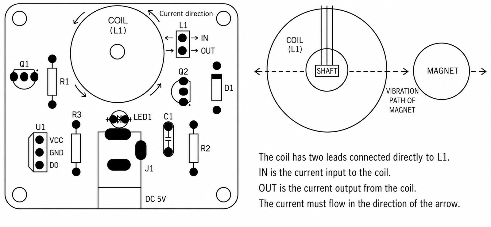
Component layout
Use this alongside the silkscreen on the board. Note the current-direction arrow around the coil, and the IN / OUT pads at L1 — the coil's two leads solder directly there, and getting them the right way round is what makes the swing push instead of pull.
What's in the kit
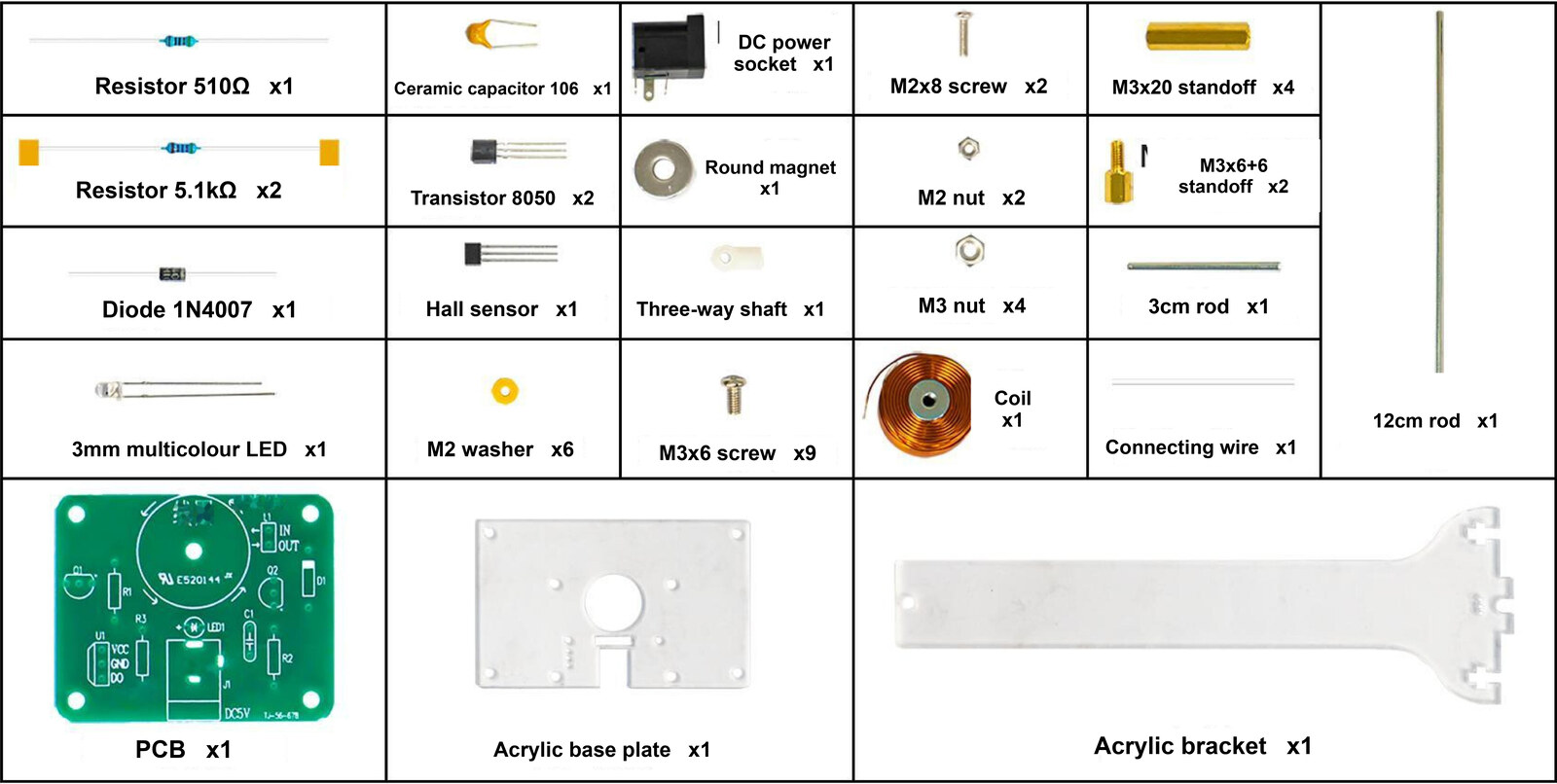
| # | Part | Specification | Reference | Qty |
|---|---|---|---|---|
| 1 | Metal-film resistor | 510 Ω | R1 | 1 |
| 2 | Metal-film resistor | 5.1 kΩ | R2, R3 | 2 |
| 3 | Monolithic ceramic capacitor | 106 — 10 µF | C1 | 1 |
| 4 | Transistor | 8050 | Q1, Q2 | 2 |
| 5 | Diode | 1N4007 | D1 | 1 |
| 6 | Through-hole multicolour LED | 3 mm | LED1 | 1 |
| 7 | Hall-effect sensor | 3144 | U1 | 1 |
| 8 | DC power socket | 5.5 × 2.1 mm | J1 | 1 |
| 9 | Coil | 1,000 turns | L1 | 1 |
| 10 | Round magnet | 12 mm diameter | — | 1 |
| 11 | Acrylic enclosure | 1 set, 2 sheets | — | 1 |
| 12 | PCB | — | — | 1 |
| 13 | Wire | — | — | 1 |
| 14 | Screw | M3 × 6 | Secures the PCB | 9 |
| 15 | Screw | M2 × 8 | Secures the acrylic bracket | 2 |
| 16 | Hex nut | M3 | Secures the PCB | 4 |
| 17 | Hex nut | M2 | Secures the acrylic bracket | 2 |
| 18 | Hex brass standoff | M3 × 6+6 (short) | Secures the PCB | 4 |
| 19 | Hex brass standoff | M3 × 20 (long) | Acrylic base legs | 4 |
| 20 | Yellow washer | M2 | — | 6 |
| 21 | Three-way shaft | 3T2AB | — | 1 |
| 22 | Steel rod | 3 cm (pivot axle) and 12 cm (pendulum) | — | 1 ea |
You'll also need
- A soldering iron (around 350 °C) and lead-free solder
- Side cutters to trim leads
- A small Phillips screwdriver and pliers for the M2/M3 hardware
- A 5 V DC power supply with a 5.5 × 2.1 mm barrel plug, centre positive
- Good ventilation or a fume extractor
Soldering technique
Preheat the pad and the lead together, feed solder in until it flows, then take the solder away and lift the iron. You're aiming for the shiny concave fillet labelled Correct joint — not a ball, not a starved joint, and definitely not a bridge across two pads.

Solder in order of height — shortest components first — so the board sits flat on the bench as you work. Resistors and the ceramic capacitor have no polarity. The diode, the LED, the transistors and the Hall sensor all do.
⚠️ One important warning
Never leave the magnet parked over the Hall sensor while the circuit is powered. If the sensor stays triggered, Q2 stays on and L1 conducts continuously — at DC an inductor is just a piece of wire, so you have effectively shorted the supply. It will overheat Q2 and the coil, and can damage your power supply. While the pendulum is actually swinging this never happens, because the sensor is only triggered for a few milliseconds per pass.
The 18 numbered steps below match the 18 numbered panels on the instruction sheet that ships in the box, so you can follow either.
Step 1 — Solder R1 — 510 Ω
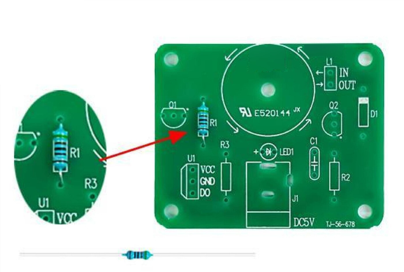
Start with the resistors — they sit lowest on the board.
R1 is 510 Ω. Its five colour bands read green, brown, black, black, brown.
- Resistors have no polarity, so either orientation is fine.
- Bend the leads down close to the body, push it into the R1 position, splay the leads slightly underneath so it doesn't fall out.
- Flip the board, solder both joints, then snip the excess leads flush.
Only one 510 Ω resistor is supplied — don't confuse it with the two 5.1 kΩ resistors in the next step.
Step 2 — Solder R2 and R3 — 5.1 kΩ
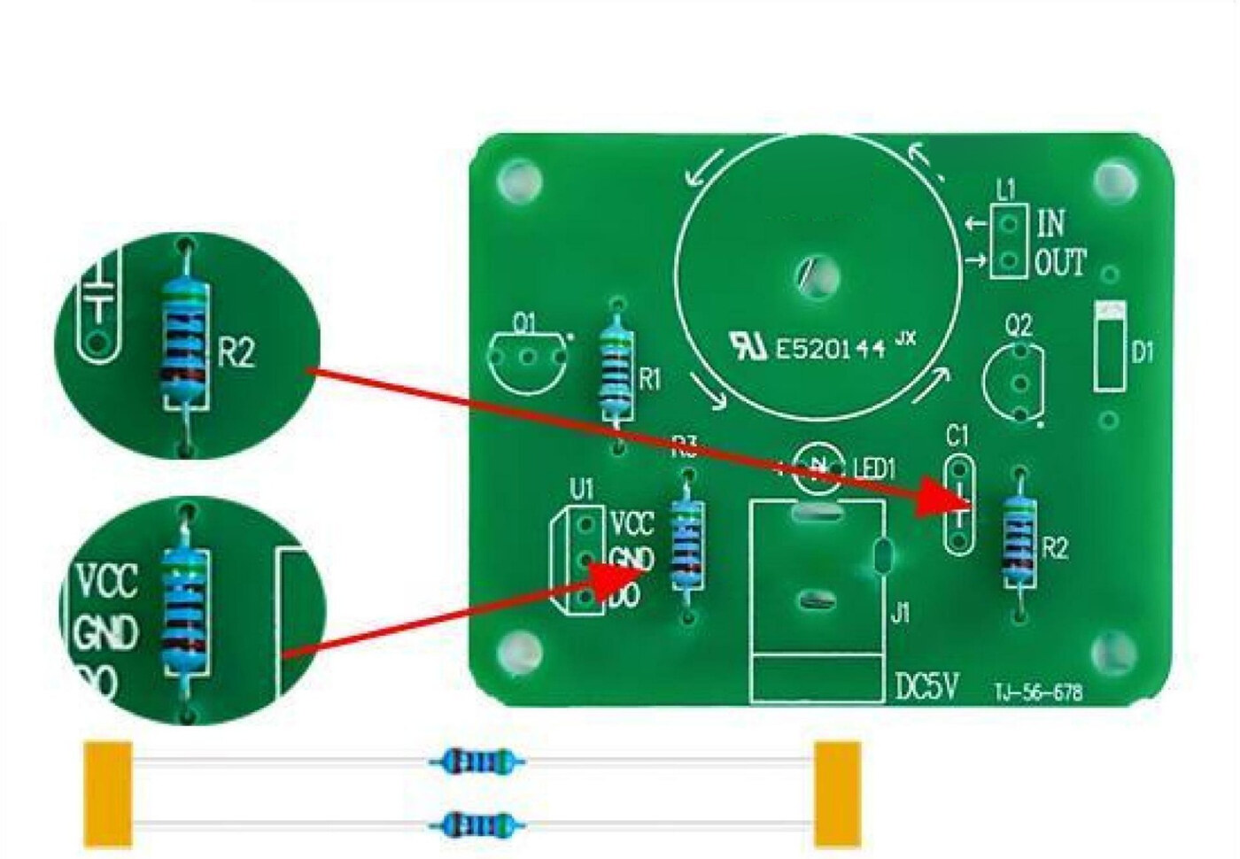
There are two 5.1 kΩ resistors, and they go in the R2 and R3 positions.
Their five colour bands read green, brown, black, brown, brown — one band different from R1, so check before you commit.
- R3 sits next to the U1 header on the lower left.
- R2 sits over on the right-hand side of the board.
- Again, no polarity — fit them either way round.
Solder and trim both before moving on.
Step 3 — Solder D1 — 1N4007 diode
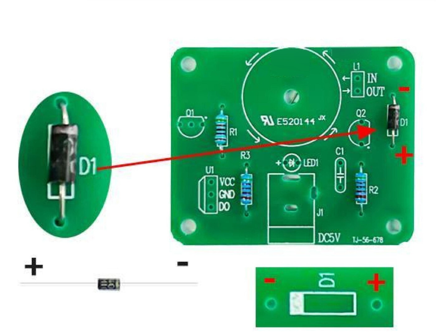
D1 is the 1N4007 — the black glass-bodied diode. This one is polarised.
- The end with the silver-white band is the cathode (negative).
- Match that band to the banded end of the outline printed on the silkscreen. The panel image shows the − and + ends.
D1 is the flyback diode. It gives the energy stored in the coil somewhere to go when Q2 switches off — without it, that collapsing field would put a large voltage spike across the transistor. Fitting it backwards means the swing won't run and Q2 has no protection, so double-check the band before you solder.
Step 4 — Solder LED1 — 3 mm colour-changing LED
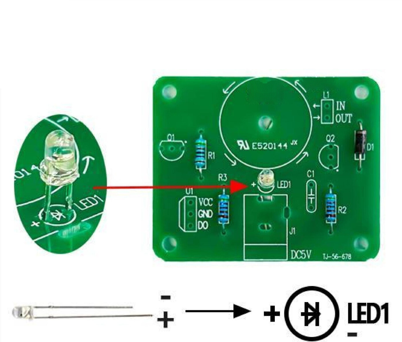
LED1 is the 3 mm multicolour (auto-cycling) LED. It is polarised:
- Long leg = positive (anode) → the + pad
- Short leg = negative (cathode) → the flat side of the silkscreen outline
Leave some height on the leads. Don't push the LED flat against the board — stand it up a few millimetres so it clears the surrounding parts and stays visible once the coil is fitted. The printed sheet in the box highlights this in red — it matters.
Solder one leg first, check it's sitting straight and at the height you want, then solder the second.
Step 5 — Solder Q1 and Q2 — 8050 transistors
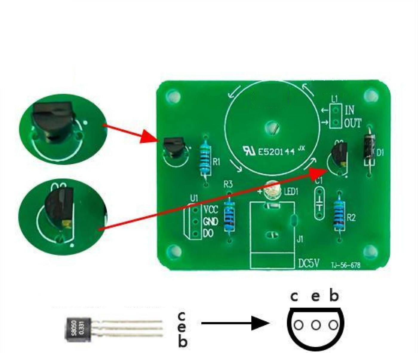
Both transistors are 8050 NPN types in a TO-92 package, and they are identical — it doesn't matter which goes in Q1 and which in Q2.
Orientation matters. Each one has a flat face with the part number printed on it and a rounded back. The silkscreen shows the same D-shape:
- Line the flat printed face up with the straight edge of the outline on the board.
- Splay the three legs slightly to match the hole spacing.
Q1 is on the left of the board, Q2 to the right of the coil. Solder all three legs on each and trim.
Step 6 — Solder C1 — 10 µF ceramic capacitor
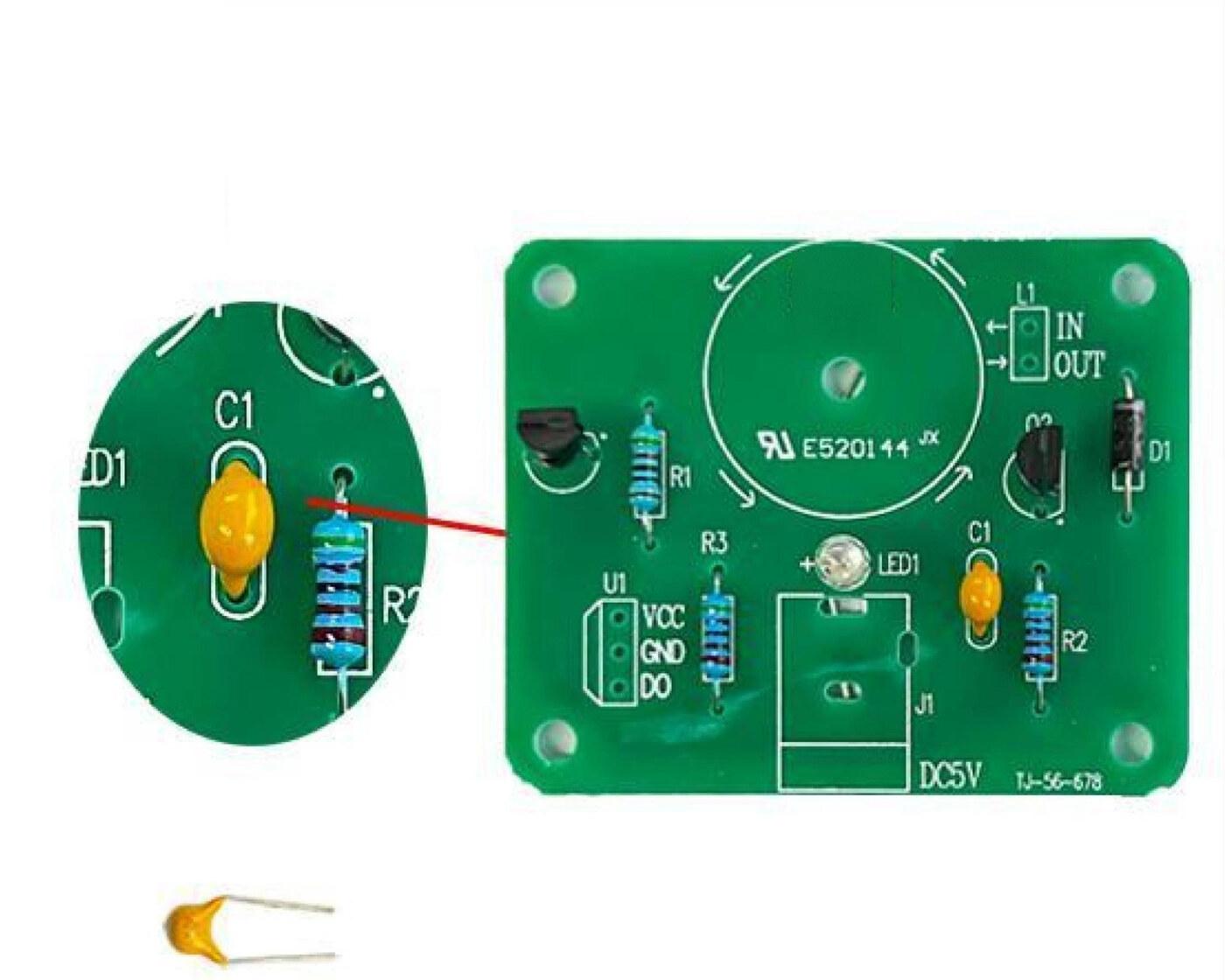
C1 is the yellow monolithic ceramic capacitor marked 106 — that code means 10 µF.
- Ceramic capacitors are not polarised, so it goes in either way round.
- Push it down so it sits close to the board, solder both legs and trim.
That's the last of the small components. At this point the board should have R1, R2, R3, D1, LED1, Q1, Q2 and C1 all fitted — everything except the DC socket and the coil.
Step 7 — Solder J1 — DC power socket
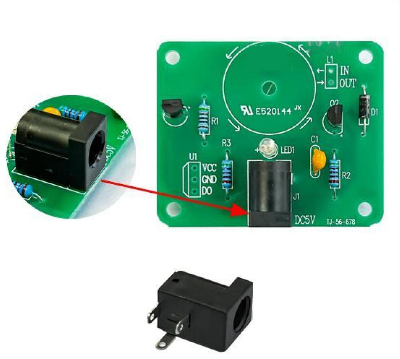
J1 is the 5.5 × 2.1 mm barrel socket, marked DC5V on the silkscreen.
- It only fits one way — drop it into the outlined footprint with the opening facing outward, overhanging the edge of the board so you can plug into it.
- Make sure it's sitting flush before you solder; once two pins are down it won't move.
These pads are much larger than the component pads, so they soak up heat. Give the iron a couple of extra seconds on each pin and feed in enough solder to fill the hole properly — a starved joint here is a common cause of a board that won't power up.
Step 8 — Solder the coil to L1 — mind IN and OUT
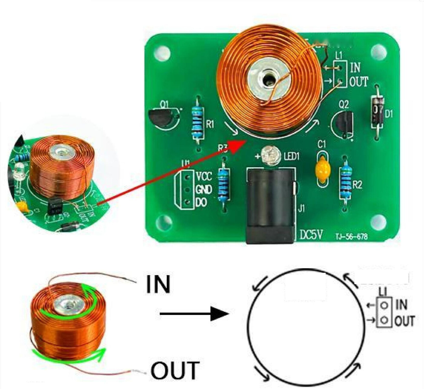
The 1000-turn coil has two leads, and they solder directly into the two L1 pads. This is the one connection where direction really matters.
- IN is where current enters the coil.
- OUT is where it leaves.
- Current has to flow the same way as the arrow printed around the coil outline on the board.
Get this backwards and the coil's field will attract the magnet rather than repel it — the pendulum will stall instead of swinging. If that happens at test time, this is the first thing to check.
The coil wire is enamelled, so scrape or tin the ends until they're bright copper before soldering.
Step 9 — Bolt the coil down and fit the short standoffs
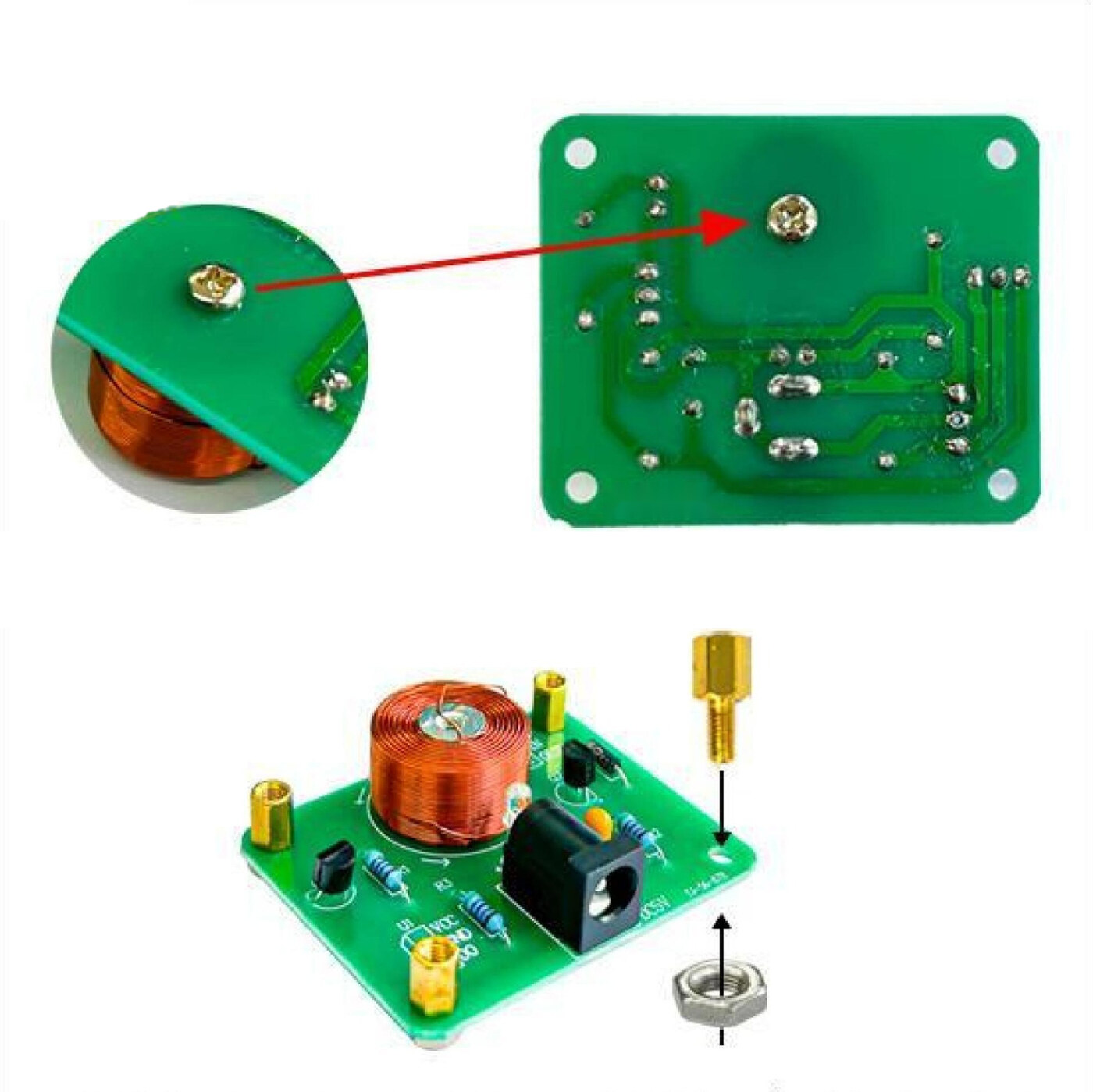
Two jobs here:
1. Fix the coil. Pass an M3 × 6 screw down through the hole in the centre of the coil and into the middle of the PCB, so the coil is clamped flat against the board and can't shift.
2. Fit the standoffs. Put the four short M3 6+6 brass standoffs into the four corner holes and lock them with M3 nuts.
These four standoffs are what the acrylic base plate will bolt onto in step 13 — so they go on the side of the board that will face up toward the base. Snug is enough; over-tightening will crack the PCB.
Step 10 — Cut and solder the three sensor wires
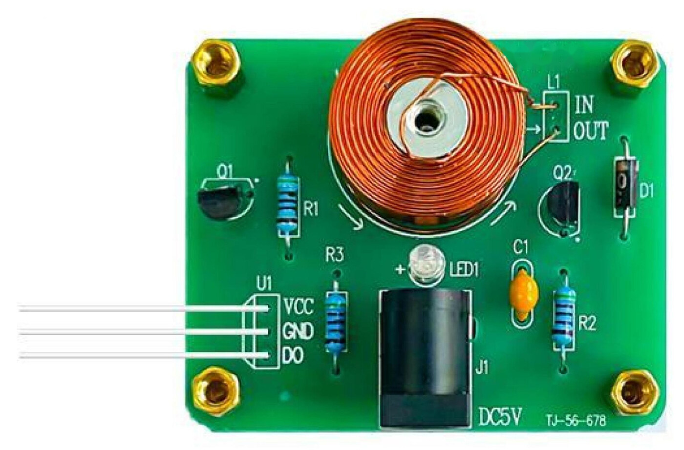
The Hall sensor doesn't live on the board — it mounts on the acrylic upright, next to where the magnet swings. Three wires carry power and signal out to it.
- Cut the supplied wire into three equal lengths.
- Strip and tin the ends.
- Solder one to each of the VCC, GND and DO pads at the U1 header.
Keep track of which wire is which — colour-code them or lay them out in order and don't let them cross. You'll be soldering the far ends onto the sensor's three legs in step 15, and getting VCC and GND swapped there will destroy the sensor.
Leave them long enough to reach up through the acrylic base with a little slack.
Step 11 — Peel the film off the acrylic parts
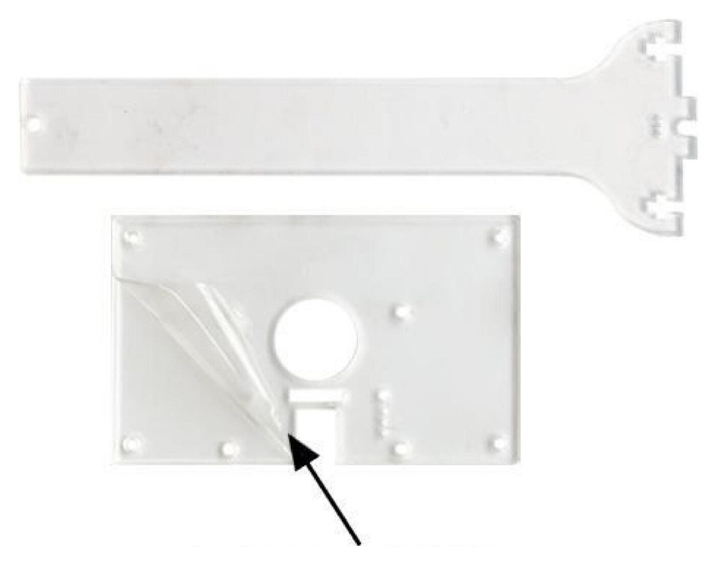
The kit includes two laser-cut acrylic pieces:
- The base plate — rectangular, with a large round hole in the middle and mounting holes at the corners.
- The upright bracket — the long T-shaped piece that becomes the tower.
Both arrive with a protective film on each side. Peel it all off now — it's easy to miss the second face and end up with a cloudy-looking build. A fingernail at a corner is usually enough to start it.
Note the three small holes near the bottom centre of the bracket: the Hall sensor's legs pass through those later.
Step 12 — Bolt the upright bracket to the base plate
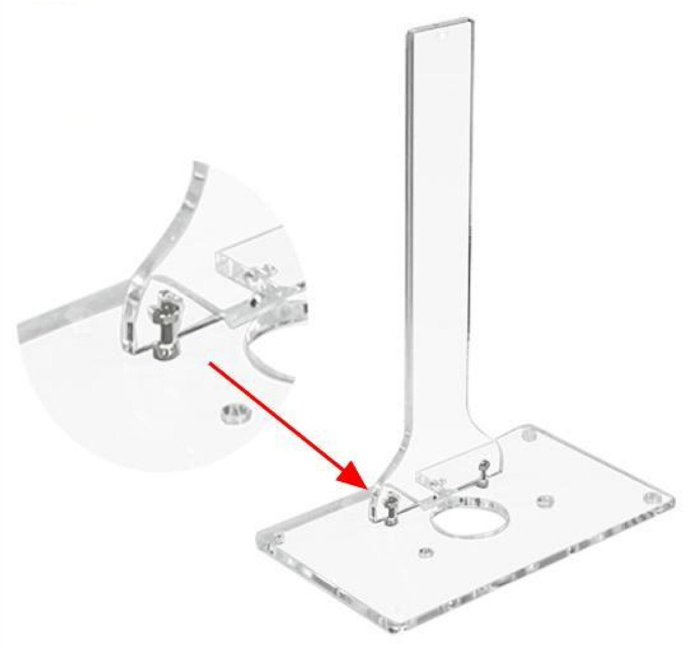
Stand the upright bracket in the slot in the base plate — the tab on the foot of the bracket drops through and the two pieces lock at a right angle.
- Secure it with the two M2 × 8 screws and two M2 nuts.
Check the tower is genuinely square to the base before you tighten. The pendulum hangs from the top of this bracket and swings directly over the coil — if the upright leans, the magnet won't pass cleanly over the sensor and the swing will run unevenly or not at all.
Acrylic is brittle: tighten until firm, then stop.
Step 13 — Mount the PCB under the base plate
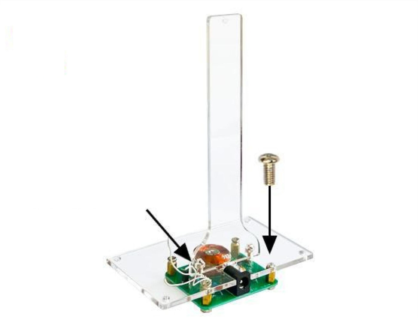
Bring the board and the acrylic assembly together.
- First, feed the three sensor wires up through the round hole in the middle of the base plate. Do this before you bolt anything down — you can't thread them afterwards.
- Line the four short standoffs on the PCB up with the four corner holes in the base plate.
- Secure with M3 × 6 screws from the top.
The coil should now sit directly beneath the acrylic base, centred under the round hole, with the upright tower rising above it.
Step 14 — Fit the long standoffs as legs
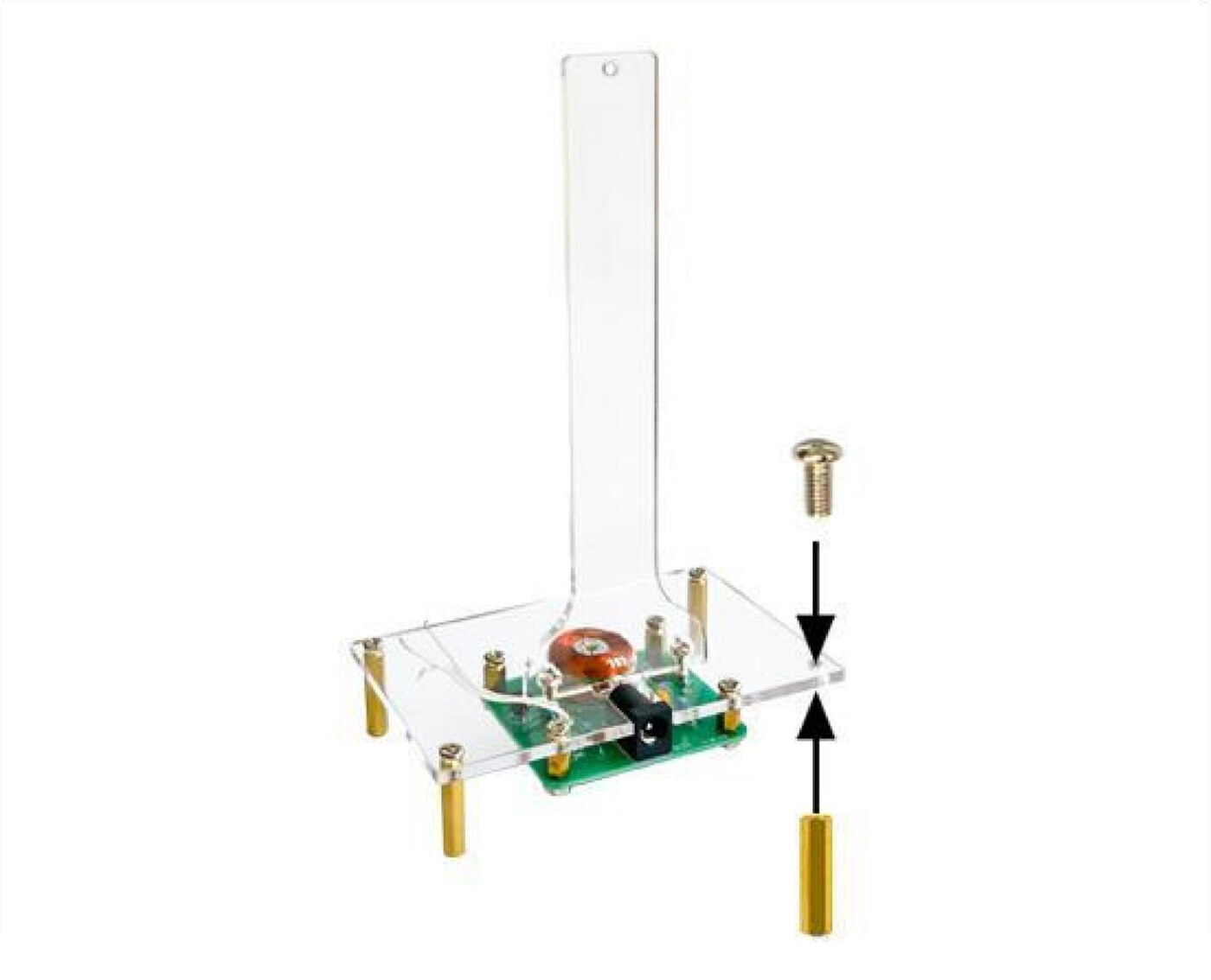
The four long M3 × 20 brass standoffs become the legs, lifting the whole assembly clear of the bench.
- Screw one into each corner, underneath the base.
- Fix them with M3 screws.
The legs aren't just decorative — they give the PCB and the barrel socket room underneath, and they keep the coil off the desk. Stand the build on a flat surface and check it doesn't rock; a wobble will show up as an uneven swing later.
Step 15 — Wire up the Hall sensor
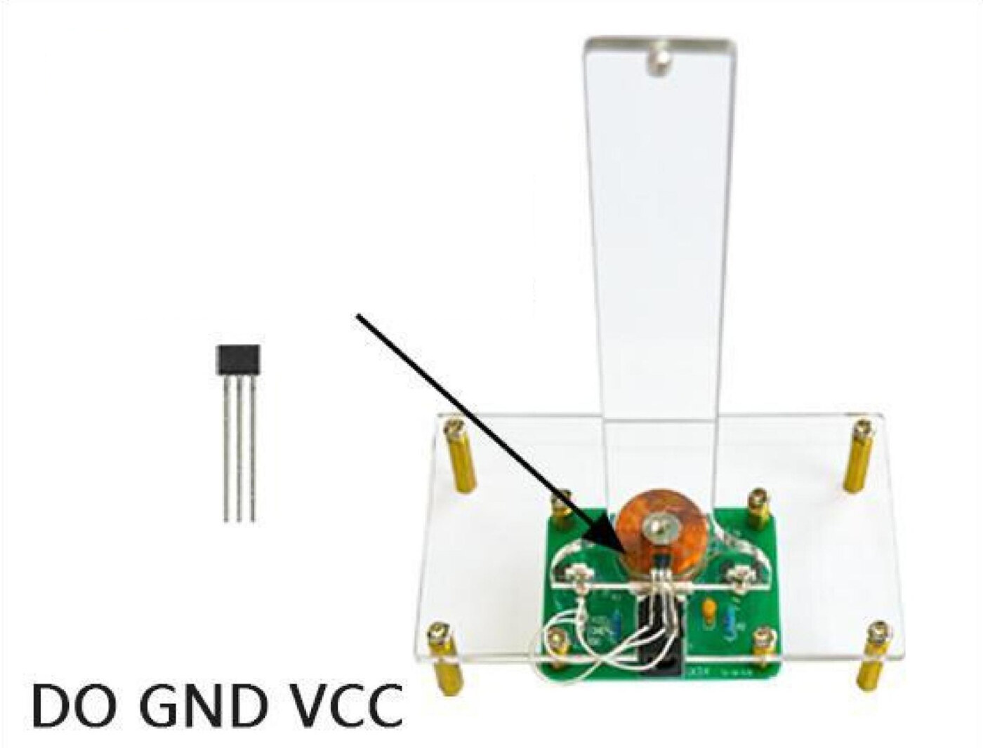
The 3144 Hall sensor mounts on the upright bracket, low down where the magnet passes.
Work out the pinout first. Hold the sensor with the legs pointing down and the narrow printed face toward you — left to right, the pins are VCC, GND, DO. (Viewed from the other side, printed face down, they read DO, GND, VCC — that's the orientation shown in the panel.)
Then mount it. The printed face must point toward the coil. Push the legs sideways through the three small holes near the bottom centre of the bracket.
Solder each of the three wires from step 10 to its matching pin: VCC to VCC, GND to GND, DO to DO. Getting VCC and GND the wrong way round will destroy the sensor, so check twice before powering up.
Step 16 — Assemble the pendulum
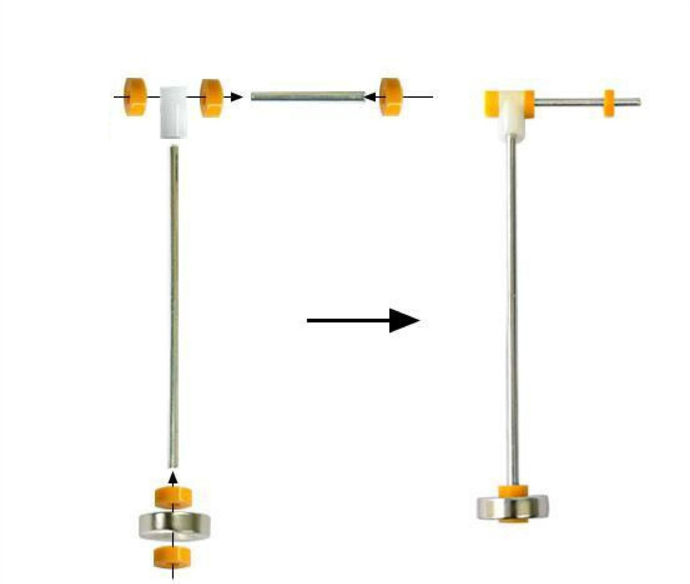
Build the swinging arm from the three-way shaft, the two steel rods, the yellow M2 washers and the magnet — following the layout in the panel.
- Push the short 3 cm rod through the cross hole in the three-way shaft. This is the pivot axle. A yellow washer goes on each side.
- Fit the long 12 cm rod into the bottom of the three-way shaft — this is the arm the magnet hangs from.
- Fit the 12 mm magnet at the bottom end of the long rod, held between washers.
Magnet orientation: fit it either face up to begin with. If the swing won't run when you test it, take the magnet off and turn it over — one face repels, the other attracts.
Everything should turn freely. Any stiffness in the pivot and the coil won't have enough push to keep it going.
Step 17 — Hang the pendulum on the bracket
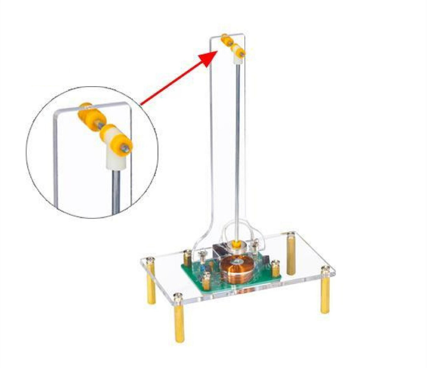
Drop the pendulum assembly onto the top of the upright bracket. The short pivot axle rests in the notch at the top, with the yellow washers either side holding it centred so it can't slide off.
Check three things:
- The arm swings freely — give it a nudge and it should keep going for a good few seconds on its own.
- The magnet passes directly over the coil at the bottom of its arc.
- The magnet passes close to the Hall sensor — near enough to trigger it, without touching.
Adjust the washer positions if the arm rubs against the acrylic.
Step 18 — The finished build
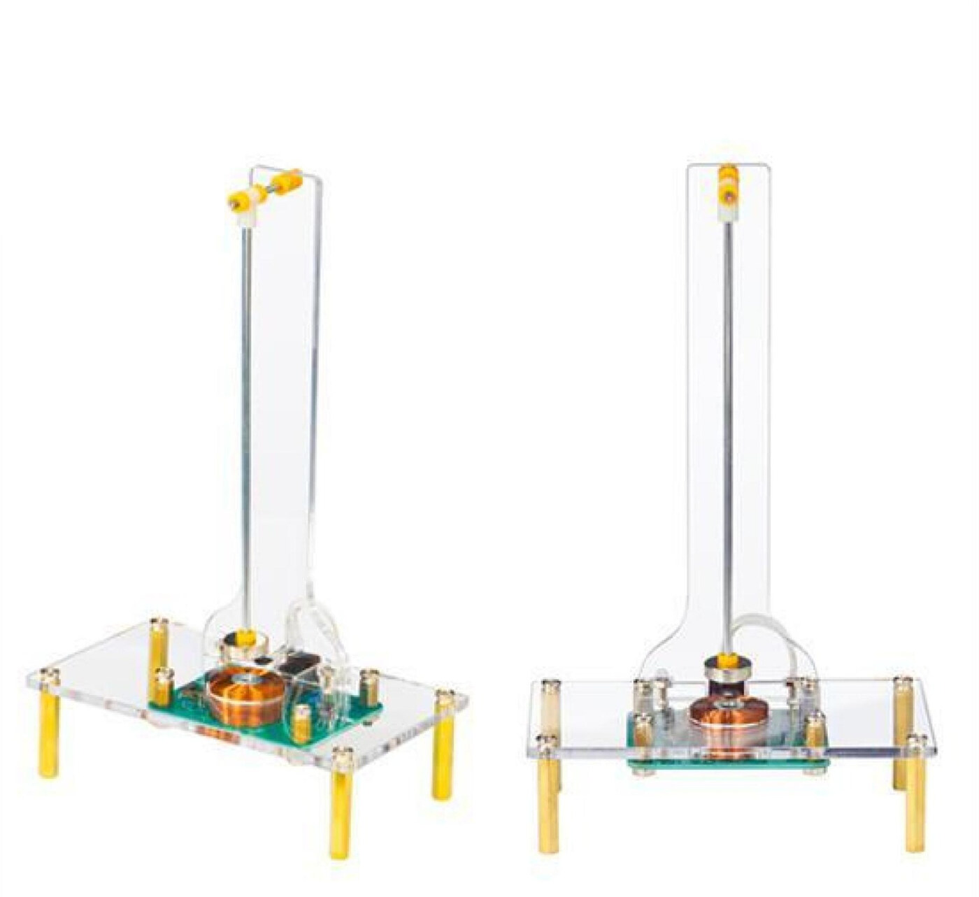
That's the assembly complete. Yours should look like this from the front and the side.
Before you apply power, run a last visual check:
- No solder bridges between adjacent pads — hold the board up to a light and look across it.
- Every lead trimmed short, with nothing touching anything it shouldn't.
- D1's band, the LED's legs and both transistors' flat faces all matching the silkscreen.
- The three sensor wires going to the right pins.
- The pendulum swinging freely and clearing the coil.
One step to go — power it up.
Step 19 — Power up and test
Plug a 5 V DC supply into the barrel socket.
- Check the LED. It should light and cycle through its colours. If nothing happens, unplug immediately and check the DC socket joints and the diode orientation.
- Test the push. Bring the magnet slowly toward the Hall sensor. At a certain distance you should feel a distinct shove against your hand. That means the coil is firing and the polarity is right.
- Set it swinging. Give the pendulum a gentle nudge. It should pick up amplitude over the first few passes and then settle into a steady, self-sustaining swing.
No push? Two things to try, in order:
- Turn the magnet over and refit it — the wrong face attracts instead of repels.
- Check the coil leads at L1 are the right way round for IN and OUT.
⚠️ Don't leave the magnet resting over the sensor while powered. Q2 stays switched on, the coil conducts continuously and effectively shorts the supply — it will get hot and can damage Q2 and your power adapter. Once it's swinging this can't happen, because the sensor only triggers for a few milliseconds per pass.
Parts List
Required Parts (1)
Everything in this guide comes in this one kit — PCB, all components, acrylic parts and hardware. You supply the soldering iron and a 5 V DC supply.
x1
$15.45
In stockProject Summary
1 part total
Unavailable items will be skipped
