

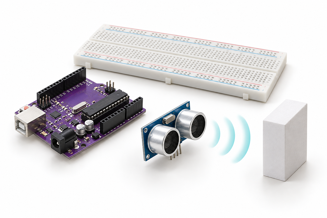
Build an ultrasonic distance meter
Explore the wiring in 3D, follow the audio explainer, and program your Little Bird Uno.
Build an ultrasonic distance meter, follow every connection in 3D, then upload the program and explore live readings. You’ll learn how echo time becomes distance and why some objects are harder to measure.
You need a Little Bird Uno, the listed sensor and jumpers, a USB data cable, and a flat object such as a book. Keep USB disconnected while wiring. No separate power supply is needed.
Step 1 — Watch the complete build
Press Play for the narrated build, or follow one connection at a time below. Drag the 3D view to inspect it; scroll to zoom. Keep USB disconnected until the wiring check.
Loading assembly…
We’ll measure how far away an object is, then watch the readings change on a graph. Leave U S B disconnected while wiring. You can drag the three D view to inspect each connection. Connect five volts on the Uno to the upper positive rail using a red jumper. The metal strip beneath this rail distributes power to the sensor without extra wires between every hole. Connect ground on the Uno to the upper negative rail with a black jumper. Ground is our shared reference and return path. Keep this rail separate from the positive rail. The ultrasonic sensor sends out a burst of sound and listens for its echo. Keep both silver transducers clear, facing your target. Female jumper sockets will fit over its four exposed header pins. Connect the sensor’s power pin to the upper positive rail with a red jumper. The female end slides onto the sensor header; the male end plugs into the breadboard. Connect the sensor’s ground pin to the upper negative rail using a black jumper. The sensor now shares the Uno’s ground, so its signal levels have the same reference. Connect digital pin seven to the sensor’s trigger input. The program sends a brief pulse here to start each measurement. Keep this blue signal wire clear of the transducers. Connect digital pin six to the sensor’s echo output. The Uno measures how long this signal stays high, then converts that time into distance. A longer echo pulse means a more distant object. Check that power and ground are separate and that trigger and echo match the program. Connect the square U S B plug to the Uno, then the other end to your computer. You’re ready to upload.
Step 2 — Meet the build
We’ll measure how far away an object is, then watch the readings change on a graph. Leave USB disconnected while wiring. You can drag the three D view to inspect each connection.
Loading assembly…
We’ll measure how far away an object is, then watch the readings change on a graph. Leave U S B disconnected while wiring. You can drag the three D view to inspect each connection.
Step 3 — See the hidden breadboard connections
The cutaway below explains the metal connections hidden inside the plastic. The terminal strips are shown in two colours to distinguish the two sides; those colours do not assign power or ground.
In this build, each rail joins the listed contacts along one side. The opposite rail does not connect automatically. If your board has a split rail, bridge the two sections only after checking which holes belong together. Never bridge positive to negative.
| From | To | Wire |
|---|---|---|
| Uno 5V | Upper + rail, hole 5 | Red |
| Uno GND beside AREF | Upper − rail, hole 5 | Black |
| Sensor VCC | Upper + rail, hole 24 | Red |
| Sensor GND | Upper − rail, hole 25 | Black |
| Uno D7 | Sensor TRIG | Blue |
| Uno D6 | Sensor ECHO | Green |
Step 4 — Connect the power rail
Connect five volts on the Uno to the upper positive rail using a red jumper. The metal strip beneath this rail distributes power to the sensor without extra wires between every hole.
Loading assembly…
Connect five volts on the Uno to the upper positive rail using a red jumper. The metal strip beneath this rail distributes power to the sensor without extra wires between every hole.
Step 5 — Connect the ground rail
Connect ground on the Uno to the upper negative rail with a black jumper. Ground is our shared reference and return path. Keep this rail separate from the positive rail.
Loading assembly…
Connect ground on the Uno to the upper negative rail with a black jumper. Ground is our shared reference and return path. Keep this rail separate from the positive rail.
Step 6 — Add the distance sensor
The ultrasonic sensor sends out a burst of sound and listens for its echo. Keep both silver transducers clear, facing your target. Female jumper sockets will fit over its four exposed header pins.
Loading assembly…
The ultrasonic sensor sends out a burst of sound and listens for its echo. Keep both silver transducers clear, facing your target. Female jumper sockets will fit over its four exposed header pins.
Step 7 — Connect sensor power
Connect the sensor’s power pin to the upper positive rail with a red jumper. The female end slides onto the sensor header; the male end plugs into the breadboard.
Loading assembly…
Connect the sensor’s power pin to the upper positive rail with a red jumper. The female end slides onto the sensor header; the male end plugs into the breadboard.
Step 8 — Connect sensor ground
Connect the sensor’s ground pin to the upper negative rail using a black jumper. The sensor now shares the Uno’s ground, so its signal levels have the same reference.
Loading assembly…
Connect the sensor’s ground pin to the upper negative rail using a black jumper. The sensor now shares the Uno’s ground, so its signal levels have the same reference.
Step 9 — Connect trigger
Connect digital pin seven to the sensor’s trigger input. The program sends a brief pulse here to start each measurement. Keep this blue signal wire clear of the transducers.
Loading assembly…
Connect digital pin seven to the sensor’s trigger input. The program sends a brief pulse here to start each measurement. Keep this blue signal wire clear of the transducers.
Step 10 — Connect echo
Connect digital pin six to the sensor’s echo output. The Uno measures how long this signal stays high, then converts that time into distance. A longer echo pulse means a more distant object.
Loading assembly…
Connect digital pin six to the sensor’s echo output. The Uno measures how long this signal stays high, then converts that time into distance. A longer echo pulse means a more distant object.
Step 11 — Connect USB
Check that power and ground are separate and that trigger and echo match the program. Connect the square USB plug to the Uno, then the other end to your computer. You’re ready to upload.
Loading assembly…
Check that power and ground are separate and that trigger and echo match the program. Connect the square U S B plug to the Uno, then the other end to your computer. You’re ready to upload.
Step 12 — How the signal works
D7 sends a 10 µs trigger pulse. D6 receives the echo pulse, and the sketch calculates distance = echo time / 58. It waits 80 ms between measurements. The reading is approximate: temperature, target angle and surface affect the returning sound.
Step 13 — Program the Uno
Use Chrome or Edge on HTTPS with a USB data cable. Choose Pair board, select Arduino Uno, then Verify and Upload. Open Serial Monitor at 115200 baud: a flat target should produce a distance in centimetres, or “No valid echo” if no reliable return is detected.
The code below is the exact sketch for D7 trigger and D6 echo. The Uno’s built-in LED lights for a valid distance below 15 cm.
Step 14 — Measure and explore
Use the same serial connection as the editor above, at 115200 baud. Hold a flat object facing the sensor and move it slowly. Compare the graph with a ruler. If readings stop changing, check Serial Monitor for “No valid echo”; a previous point is not a new measurement.
Step 15 — Try, predict and compare
- Hold a flat book about 20 cm from the transducers. Compare the reading with a ruler measured from the sensor face.
- Move to about 40 cm. Predict whether the echo time should double, then compare the plot.
- Move inside 15 cm, keeping more than 2 cm away. The Uno’s built-in LED should turn on. Move beyond 15 cm; it should turn off.
- Tilt the book away, then try a soft cloth. Observe why some surfaces give unstable readings or no echo.
Keep a record of actual distance, displayed distance and target surface. A missing echo is an unknown reading; do not treat it as an object touching the sensor.
Step 16 — Troubleshoot your build
| What you see | What to check |
|---|---|
| No valid echo | Try a large flat target facing the sensor, about 20–100 cm away. Check TRIG on D7, ECHO on D6, 5V and ground. |
| Jumping values | Keep wires and fingers away from the transducers. Change the target angle and avoid nearby surfaces reflecting sound. |
| No serial output | Use a USB data cable, select the Uno, upload successfully and connect at 115200 baud. Close other applications using the same serial port. |
| LED threshold seems wrong | Measure from the sensor face. This sketch lights the built-in LED only for a valid positive reading below 15 cm. |
This wiring is for a 5V Uno. The sensor’s echo output must not be connected directly to a 3.3V-only input without suitable level shifting.
Parts List
Required Parts (6)

Four female-to-male jumpers for the sensor header
x1
$2.20
In stock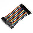
Two male-to-male jumpers for the breadboard power rails
x1
$2.20
In stock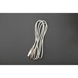
USB-A to USB-B data cable connects the Uno to your computer
x1
$2.00
In stockProject Summary
6 parts total
Unavailable items will be skipped
