


Assembling the five-pointed star LED kit
Build the fifty-LED colour-changing star step by step. The resistors, chip socket, power jack and switch go on one side, the fifty colour-cycling LEDs on the other, and any USB port runs it.
What you’re building
Fifty LEDs arranged in a star run through light patterns, and every LED changes colour as it goes. It’s a step up from a first soldering kit: about 160 through-hole joints, a 28-pin chip socket, and one catch that trips people up: parts go on both sides of the board.
How the circuit works
The brain is an STC15F204EA, an 8051-family microcontroller that comes with its light-show program already loaded. Twenty-five of its pins each control a pair of LEDs. When the program pulls a pin low, current flows from the 5 V supply, through a 1 kΩ resistor, through each LED in that pair and into the pin. The program switches the pins in sequence, and that makes the light run round the star.
The ten resistors are shared: each one feeds one LED in five different pairs, so ten is enough for all fifty.
The LEDs make the colours themselves. Each one is a colour-cycling (“seven-colour fast-flash”) LED with a tiny controller inside that steps through seven colours whenever it has power. Neighbouring LEDs drift out of step with each other, so the star never looks quite the same twice.
Power comes in through the DC jack from the included USB lead, via a latching push switch. Any USB port or USB phone charger will run it.
Tools you’ll need
- A soldering iron and solder. Use decent solder: cheap solder doesn’t flow properly and leaves dry joints that come back to haunt you.
- Side cutters, for trimming leads flush.
- A small screwdriver, for the four standoff screws.
- A USB port or USB phone charger. The USB-to-DC lead is in the kit.
- Optional: a blob of Blu Tack or masking tape to hold parts in while the board is upside down.
What’s in the kit
| Qty | Part | Position | How to identify it |
|---|---|---|---|
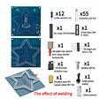
| 12 | 1 kΩ resistor | R1–R10, plus 2 spare | brown-black-black-brown-brown (5-band) or brown-black-red-gold (4-band) |
| 55 | Colour-cycling LED, 5 mm | D1–D50, plus 5 spare | clear lens, polarised: long leg is positive |
| 1 | STC15F204EA microcontroller | U1 | 28 pins, pre-programmed, notch at one end |
| 1 | 28-pin IC socket | U1 | notch at one end |
| 1 | Latching push switch | right-hand edge | steel body, button on a long stem; press on, press off |
| 1 | DC barrel jack (DC002) | right-hand edge, below the switch | black, three pins, the power input |
| 1 | 4-pin header, 2.54 mm | J1, below the chip | optional, only needed to reprogram the chip |
| 1 | USB to DC power lead | — | 0.8 m, USB-A to barrel plug |
| 4 | M3 × 10 mm brass standoffs | corner holes | the feet |
| 4 | M3 × 6 mm screws | corner holes | hold the standoffs on |
| 1 | PCB | — | printed MH-T12 on the component side |
Check everything against this list before you pick up the iron. Leftover resistors and LEDs at the end are the spares, not a mistake.
Four rules that save the build
- Two sides, no exceptions. Everything except the LEDs goes in from the side printed MH-T12 and is soldered on the star side. The fifty LEDs go in from the star side and are soldered on the MH-T12 side. A part on the wrong face has to be desoldered to fix it.
- Follow the order. Resistors, IC socket, power jack, switch and header first, then the LEDs. The small parts go in while the board can still lie flat.
- Watch the polarised parts. LEDs (long leg positive) and the chip and socket (notch to notch, towards the star’s top point). Resistors don’t care which way round they go.
- Test after the first LED. Solder one LED, plug in and check that it flashes. If you’ve got the polarity wrong, you find out on one LED instead of fifty.
If it doesn’t work
| Symptom | What to check |
|---|---|
| Nothing lights at all | The switch is latched in; the lead is pushed fully into the jack; the USB port or charger is live; the chip is the right way round with every pin in the socket |
| One LED never lights | That LED is in backwards (long leg to +), or one of its two joints is dry |
| Two LEDs with consecutive numbers stay dark together, e.g. D9 and D10 | They share one chip pin. Look for a pin folded under the chip or a bridged or dry socket joint |
| Five LEDs stay dark, every other one along a run, e.g. D2, D4, D6, D8, D10 | They share one resistor. Check that resistor’s two joints |
| Neighbouring LEDs show different colours | Normal. Each LED cycles its own colours and they drift apart |
| The chip gets warm, or the charger cuts out | Unplug straight away. Check the chip’s orientation, then look for solder bridges, especially between socket pins and the closely packed LED pads |
Step 1 — Learn the two sides of the board first
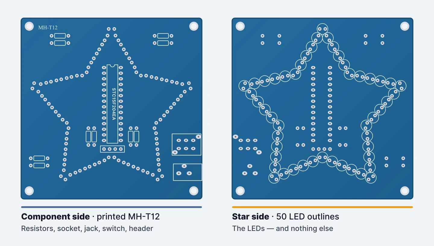
This board has parts on both faces, so work out which is which before you start.
The side printed MH-T12, with the chip outline in the middle, is the component side. The resistors, IC socket, power jack, switch and header go in from here.
The other face, with fifty circles printed in a star, is the star side. Only the LEDs go in from there.
Every part is soldered on the face opposite the one it sits on.
Step 2 — Check the parts
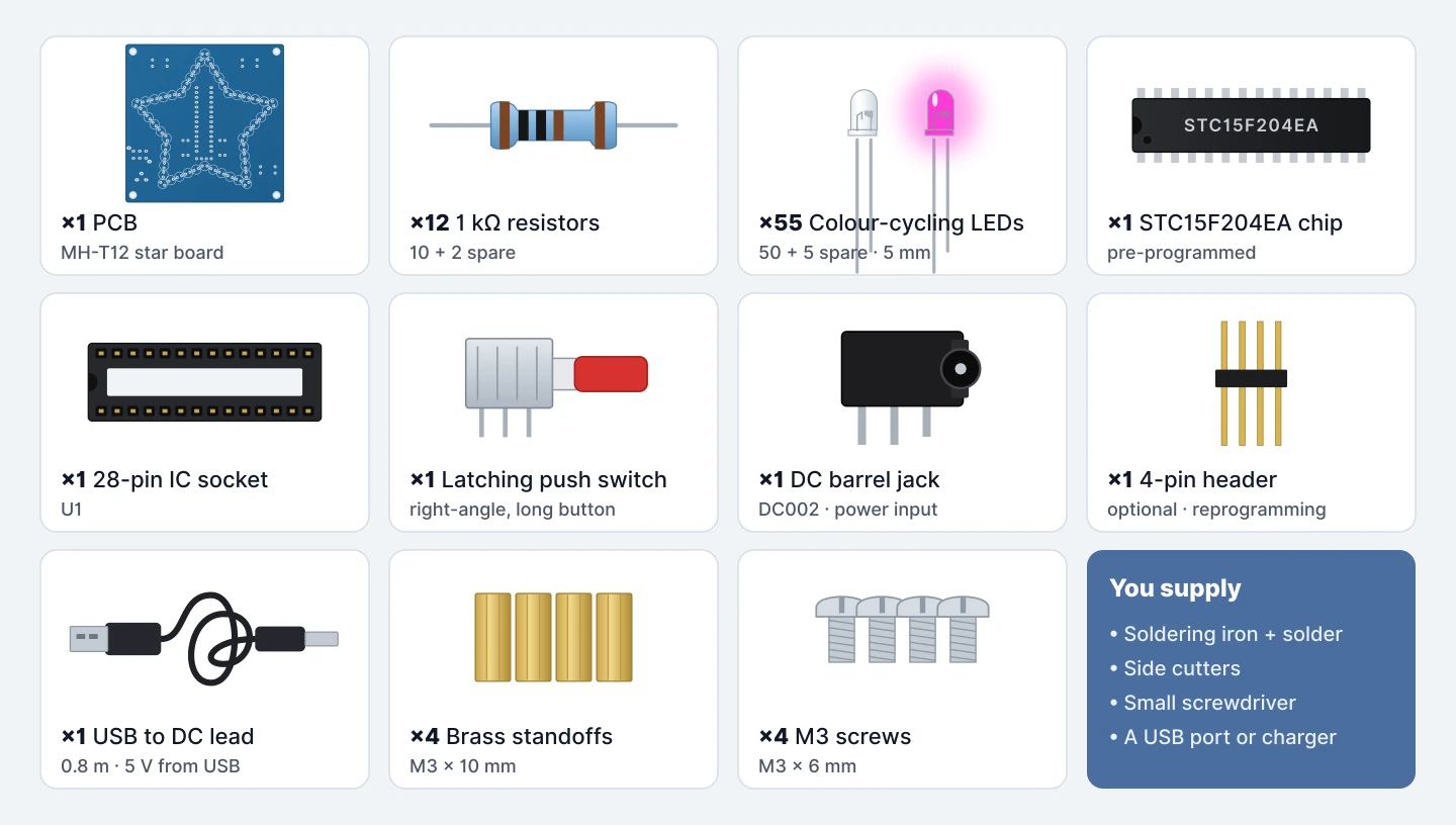
Lay everything out and check it against the parts table above.
The kit includes two spare resistors and five spare LEDs, so you’ll have a few left over at the end. Sort out anything that’s missing before you pick up the iron.
Step 3 — Every resistor is the same
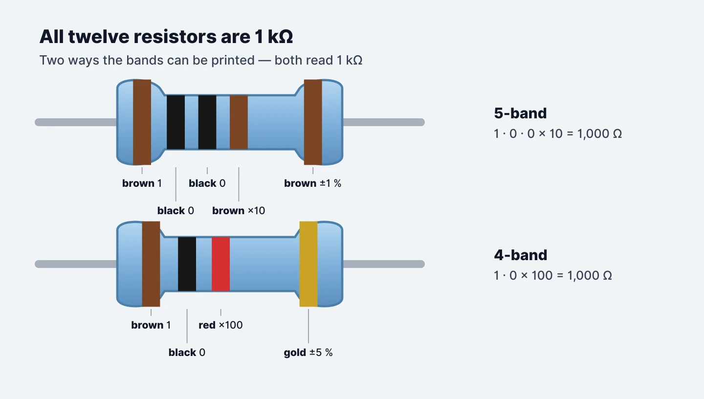
All twelve resistors are 1 kΩ: ten to fit and two spares. Because they’re all the same value, any resistor can go in any position.
Colour code: brown-black-black-brown-brown (5-band) or brown-black-red-gold (4-band).
Step 4 — Fit the ten resistors on the MH-T12 side
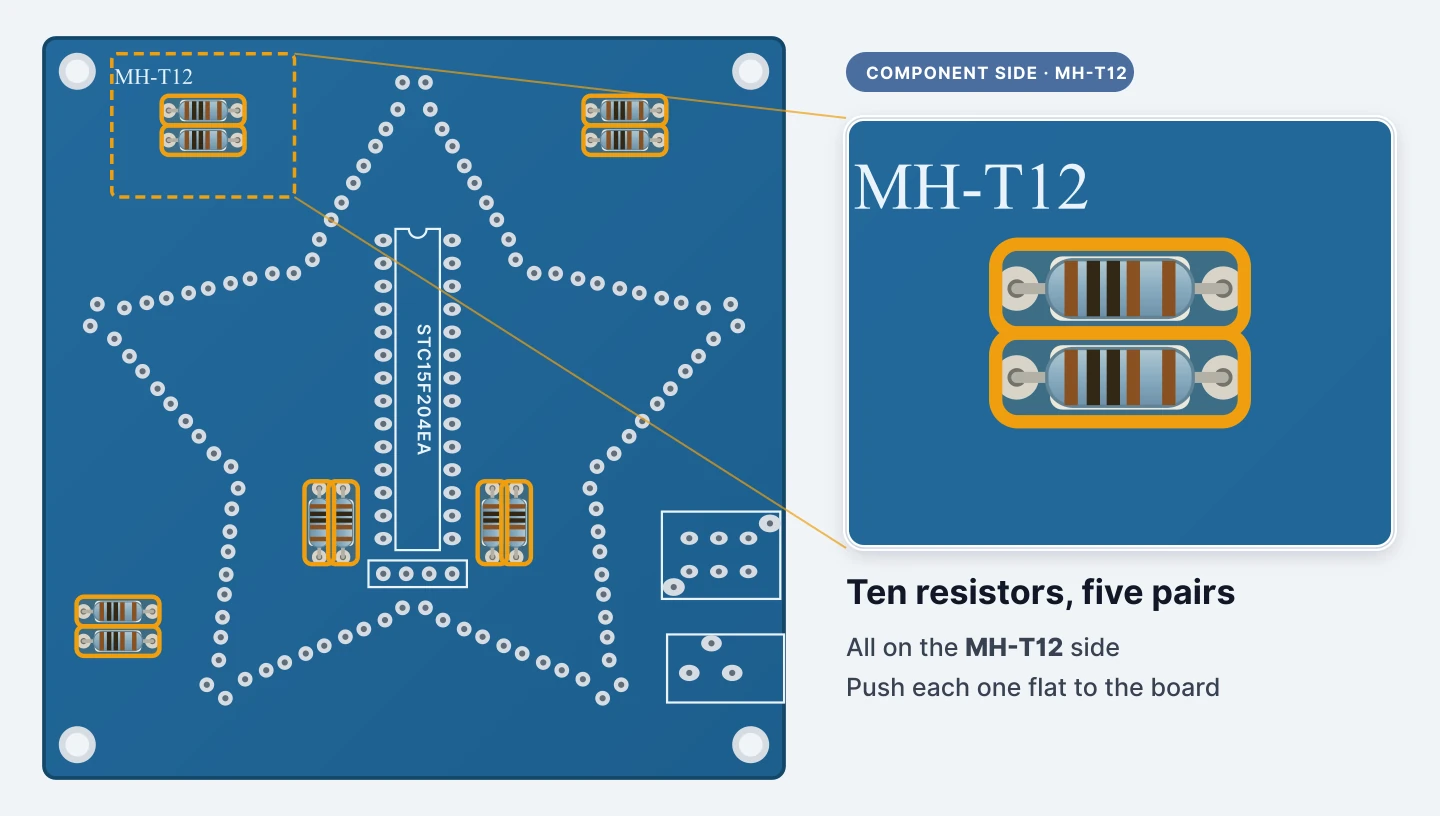
The resistors sit in five pairs: top left, top right, bottom left, and one pair on each side of the chip outline.
Push each one through from the MH-T12 side, then bend its legs outwards on the star side so it can’t drop out. Press the body flat against the board. Resistors aren’t polarised, so either way round is fine.
Step 5 — Solder the resistors on the star side
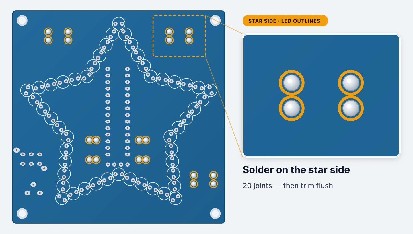
Turn the board over and solder all twenty joints. Each one should be full and rounded, not a dull blob sitting on the pad.
Snip every leg flush with its joint.
Step 6 — Fit the 28-pin socket, notch to the top
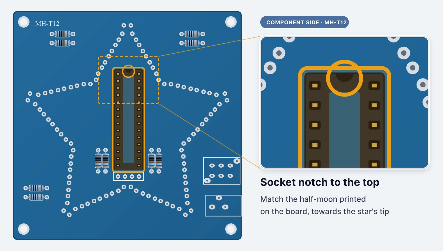
The socket goes into the long outline in the middle of the MH-T12 side.
The socket and the printed outline both have a half-moon notch at one end, and they must line up. On this board the notch points towards the star’s top point.
Fit the socket now and leave the chip out. The chip pushes in later, well away from the heat.
Step 7 — Tack two opposite corners first
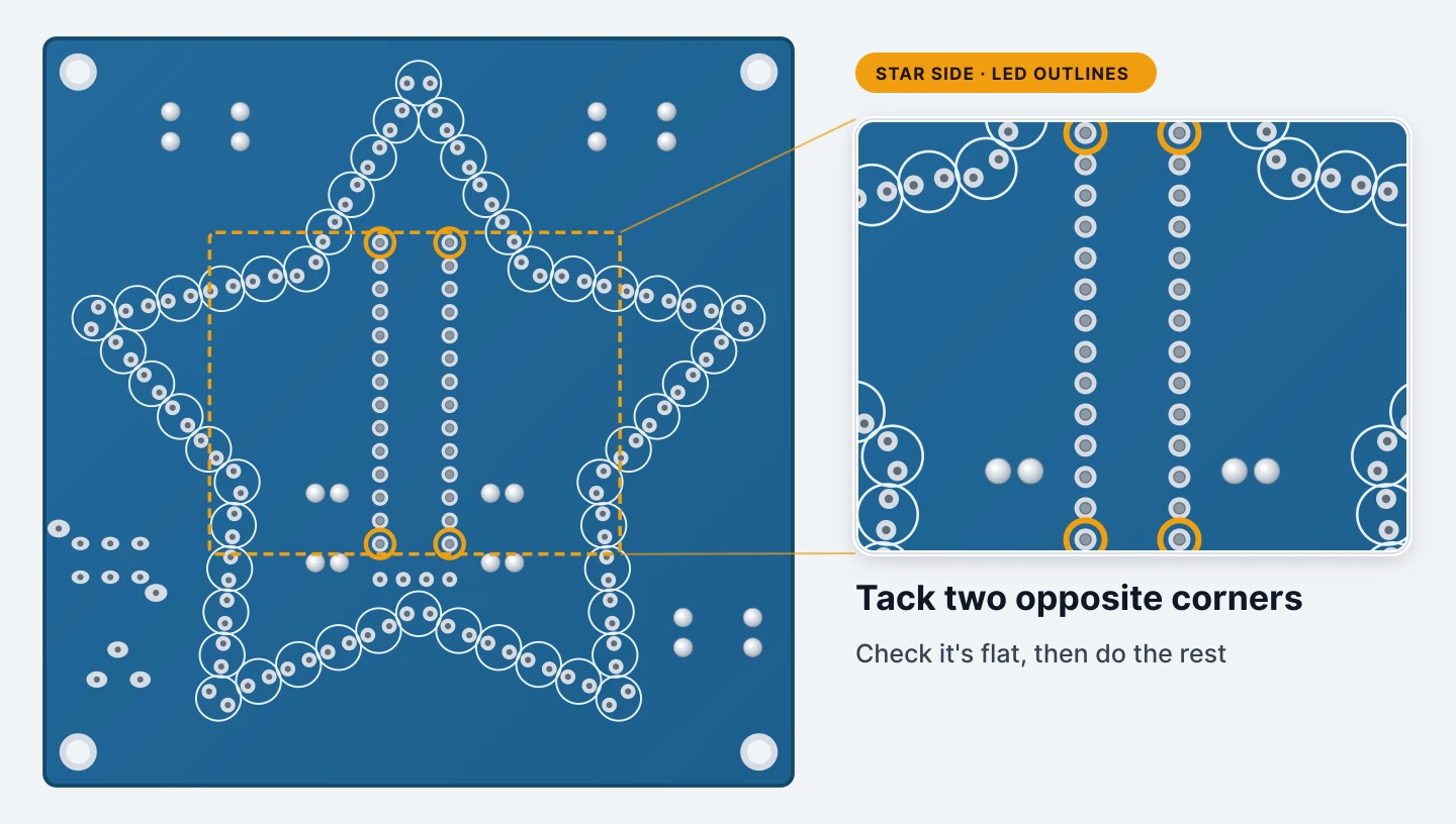
Hold the socket against the board (a blob of Blu Tack helps with the board upside down) and solder two diagonally opposite corner pins.
Check the socket is sitting flat. If one end has lifted, reheat that corner and press it down before you go on.
Step 8 — Solder the other 26 pins
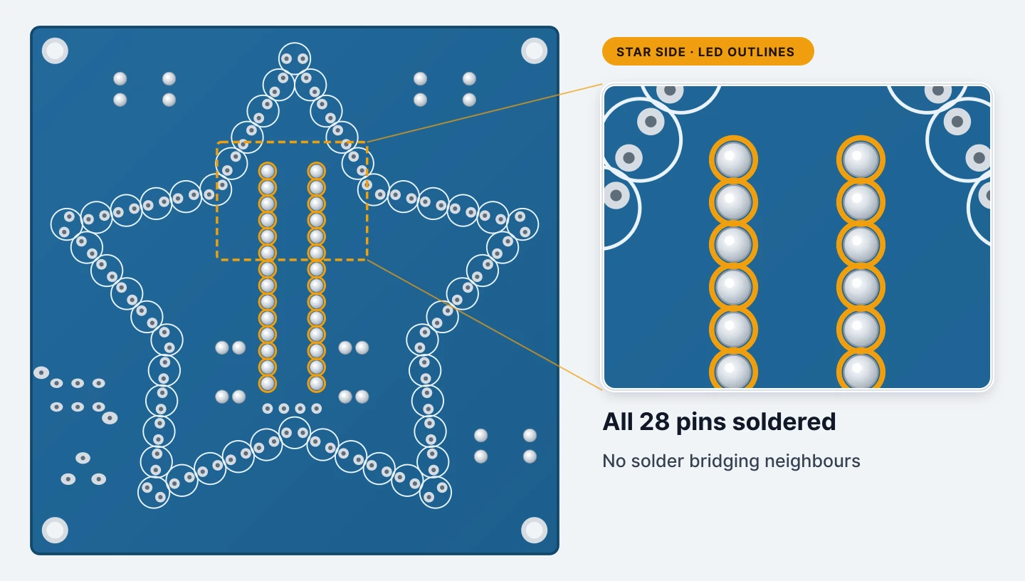
Work down each row. The pins are only 2.54 mm apart, which is where solder bridges happen.
When you’re done, check that no two neighbouring joints have run together. If they have, drag the iron between them to separate them.
Step 9 — Fit the power jack
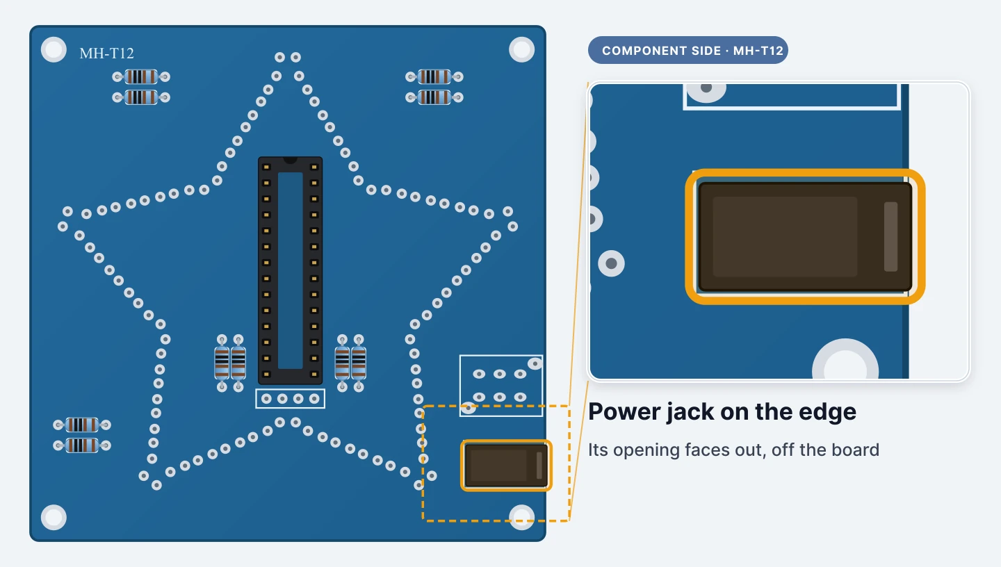
The DC jack goes in the lower outline on the right-hand edge of the MH-T12 side.
Its round opening faces out over the edge of the board, where the plug can reach it. Push it right down until the body sits flat.
Step 10 — Fit the push switch
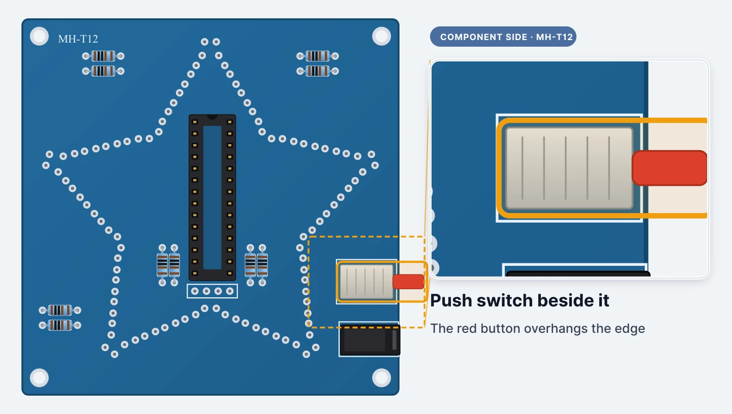
The switch goes in the rectangular outline just above the jack. It lies on its side, and the button on its long stem reaches out past the edge so you can press it.
It’s a latching switch: press once for on, and again for off.
Step 11 — Solder the switch and jack
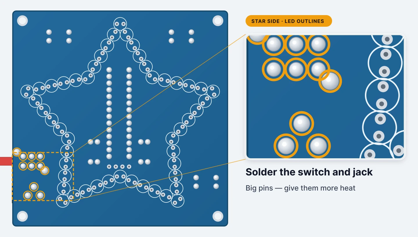
Turn the board over. These pins are much chunkier than a resistor leg, so hold the iron on each one for a few seconds longer and feed in enough solder to fill the hole.
The switch has two larger mounting tabs as well. Solder those too, because they’re what keep it steady when you press the button.
Step 12 — Optional: fit the 4-pin header
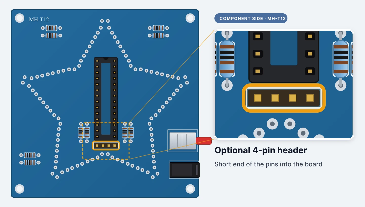
The header is only for loading a new program into the chip (see the last step), so you can leave it out.
If you fit it, it goes in the small outline below the chip on the MH-T12 side, with the short end of the pins into the board and the long end pointing up.
Step 13 — Solder the header
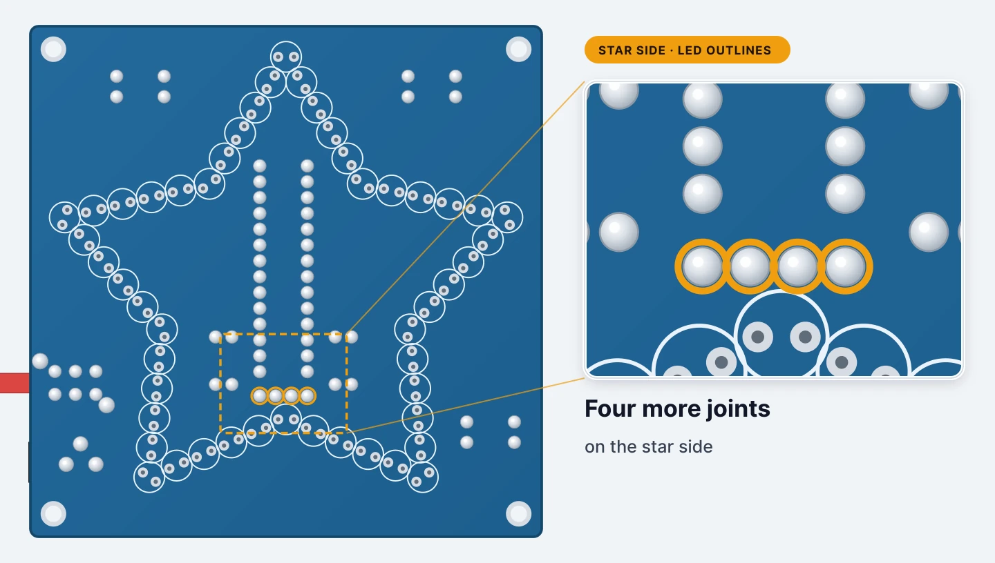
Four joints on the star side. Tack one pin, check the header is standing straight, then solder the other three.
Step 14 — Push the chip into its socket
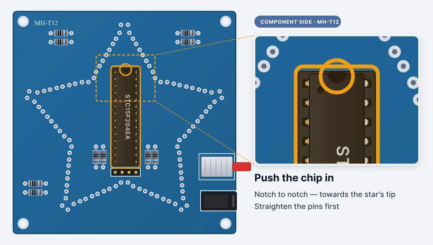
Match the chip’s notch to the socket’s notch, towards the star’s top point.
If the two rows of pins splay outwards, roll them gently against the table until they’re parallel. Line every pin up with its hole, check none has folded under, then press down evenly with your thumb.
The kit’s paper sheet fits the chip last. We fit it now so you can test the first LED in a few steps’ time. None of the joints still to come are on the chip’s own pins, and they’re all out round the star.
Step 15 — Meet the colour-changing LEDs
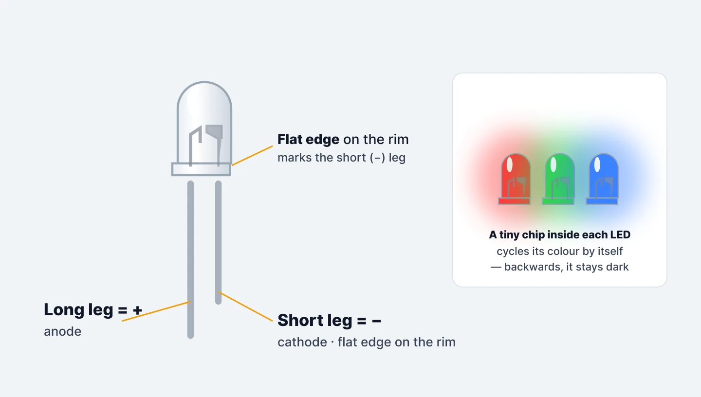
Each LED has a tiny chip inside that cycles its own colour. That chip only works one way round, so the LEDs are polarised.
The long leg is positive (+). The short leg is negative, and the rim of the LED usually has a flat edge on that side too.
The LEDs go in from the star side, into the fifty printed circles.
Step 16 — Fit one LED at the top point
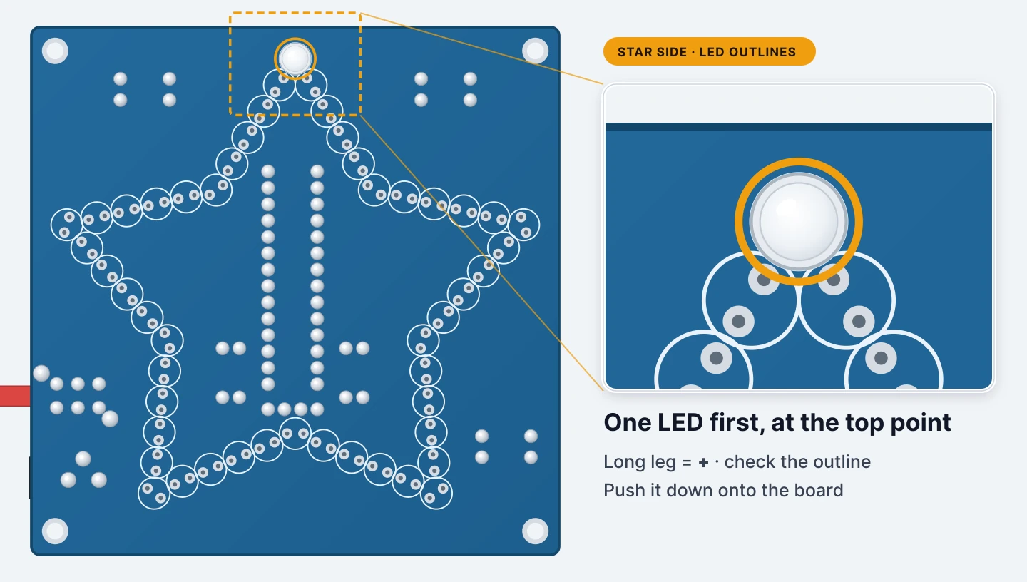
Start with just one, at the star’s top point.
Look closely at its printed circle. LED outlines usually mark polarity with a small + or a flat edge. The long leg goes to +, and the LED’s flat rim lines up with the flat edge.
Push it down until the rim sits on the board.
Step 17 — Solder it on the MH-T12 side
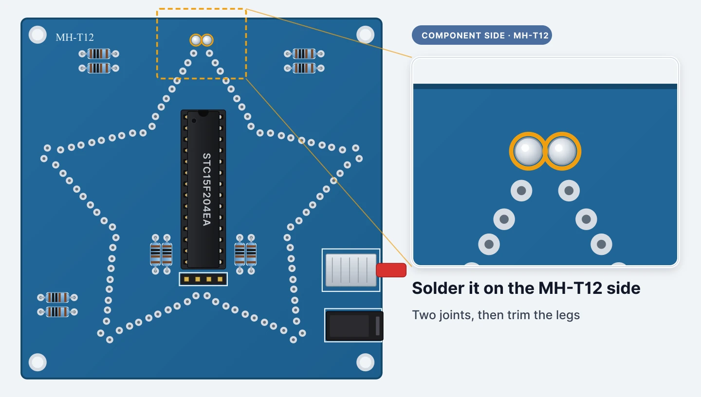
Turn the board over, solder the LED’s two legs and trim them.
Step 18 — Test that one LED
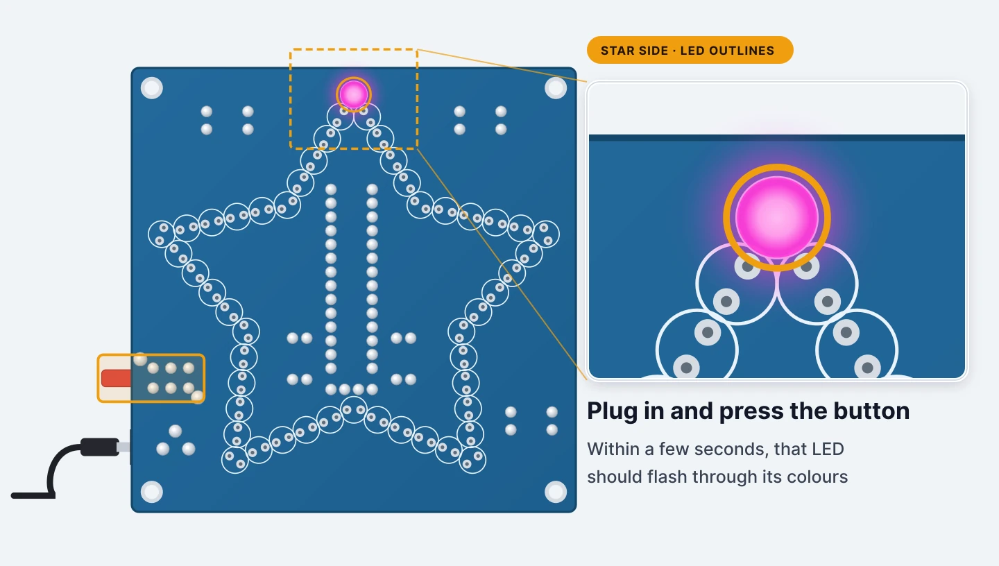
Plug the USB lead into the jack and into a USB port or charger, then press the button. Give the pattern a few seconds to come round, and the LED should flash through its colours.
If it stays dark, unplug it, desolder the LED, turn it round and test again. Once it works, you know which way the other forty-nine go.
Press the button to switch off and unplug before you carry on soldering.
Step 19 — Fill in the rest of the top point
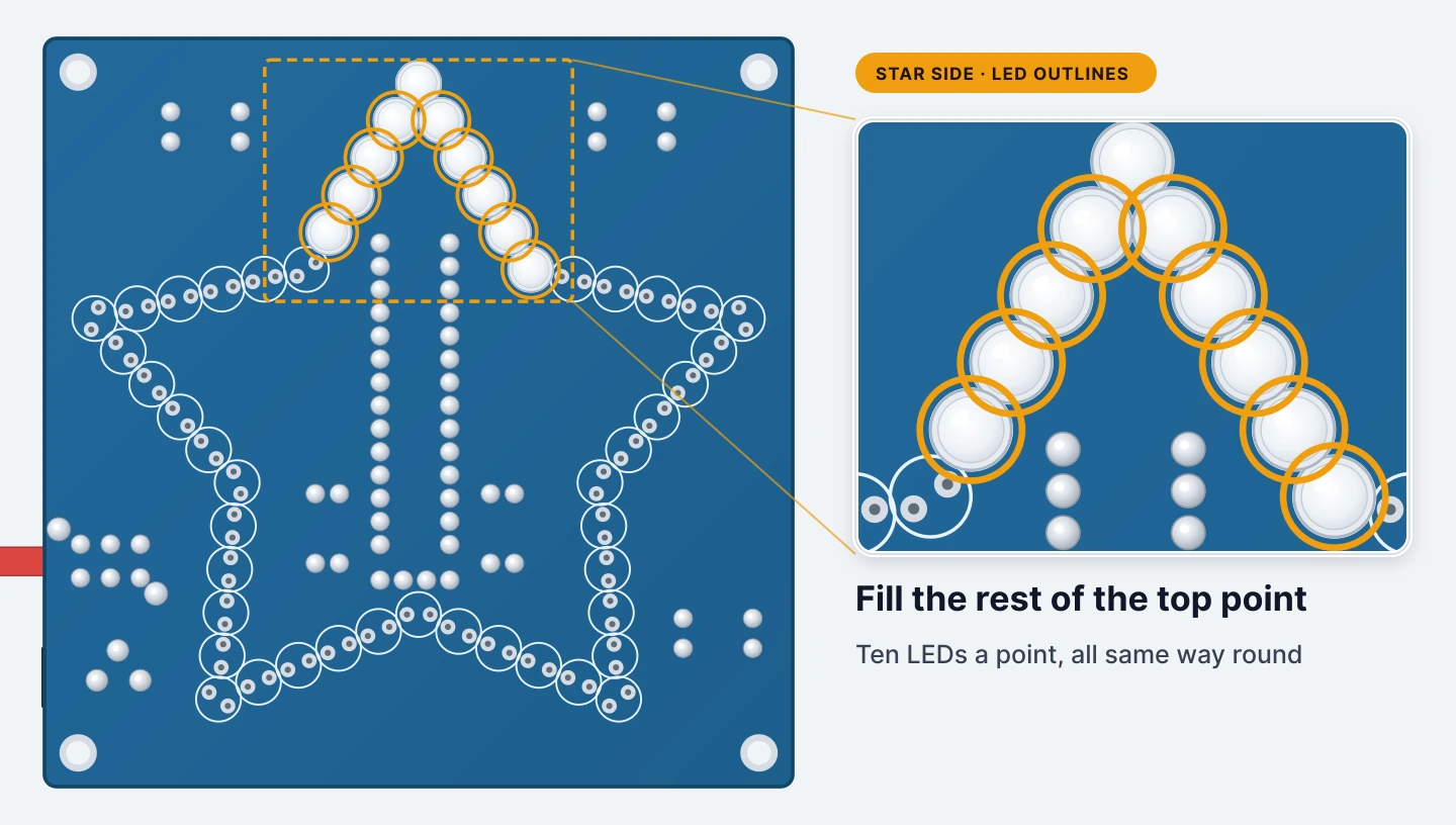
Work one star point at a time, ten LEDs to a point.
Fit the other nine the same way round as the one you tested, and push each one down flat. Bend the legs slightly outwards underneath so they stay put when you turn the board over.
Step 20 — Solder one leg of each, straighten, then the second legs
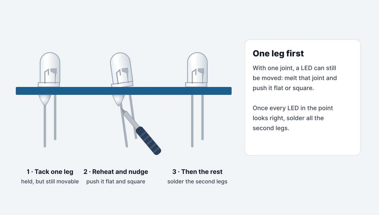
For a neat star, solder just one leg of every LED in the point first.
Then look along the row from the side. If an LED is leaning or sitting high, reheat its one joint and push it into place.
When the whole point looks right, solder all the second legs and trim.
Step 21 — Work round the star, one point at a time
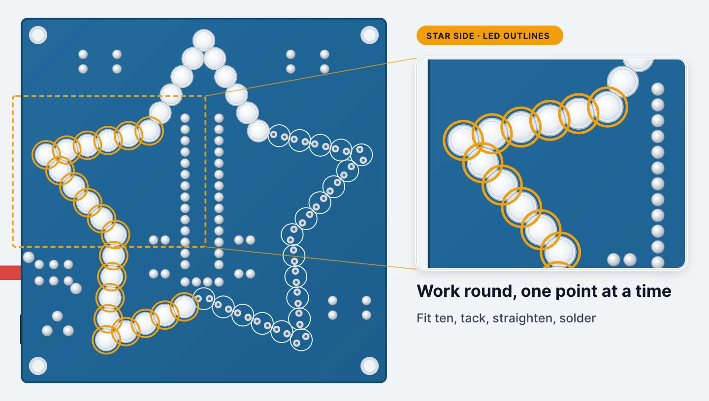
Repeat for the other four points: fit ten, tack one leg each, straighten, solder the second legs, trim.
Doing a point at a time stops the underside turning into a forest of legs.
Step 22 — All fifty LEDs in
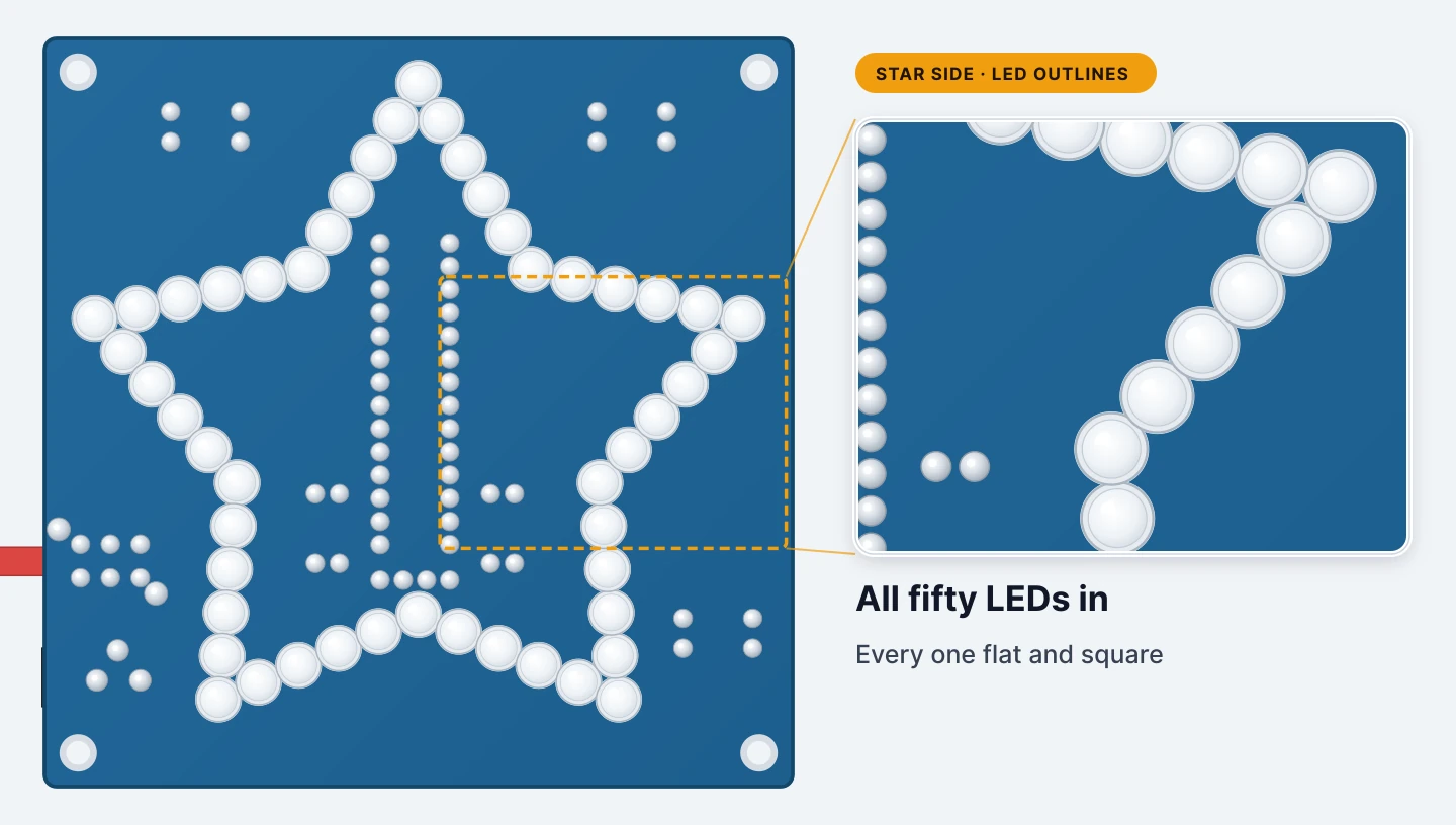
Look across the star from the side. Every LED should be sitting on the board and standing square.
Step 23 — Inspect the LED joints
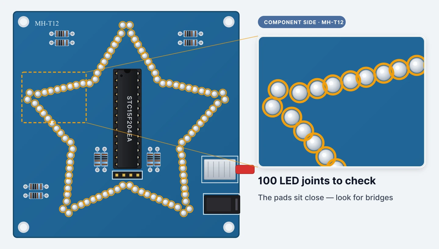
That’s a hundred joints. The LEDs are packed tightly, so their pads are close together.
Look for any joint that has run into its neighbour, and any that look dull or haven’t filled the hole. Fix them now, before the board goes on its feet.
Step 24 — Fit the four standoffs
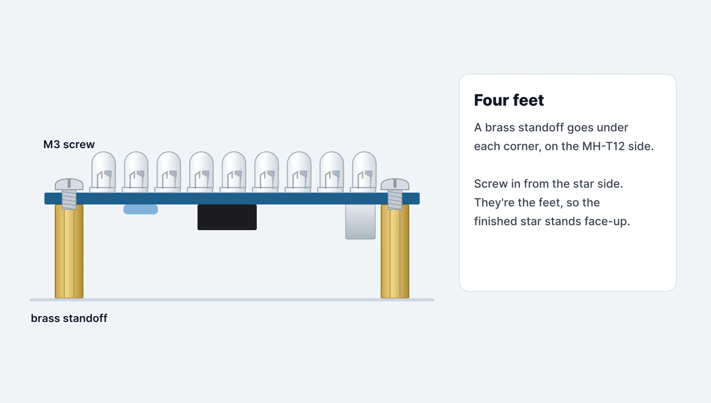
Put a brass standoff under each corner hole on the MH-T12 side, and screw an M3 screw into it from the star side.
Snug is enough, so don’t crank them down. The standoffs are the feet that let the finished star stand face-up.
Step 25 — Plug in and switch on
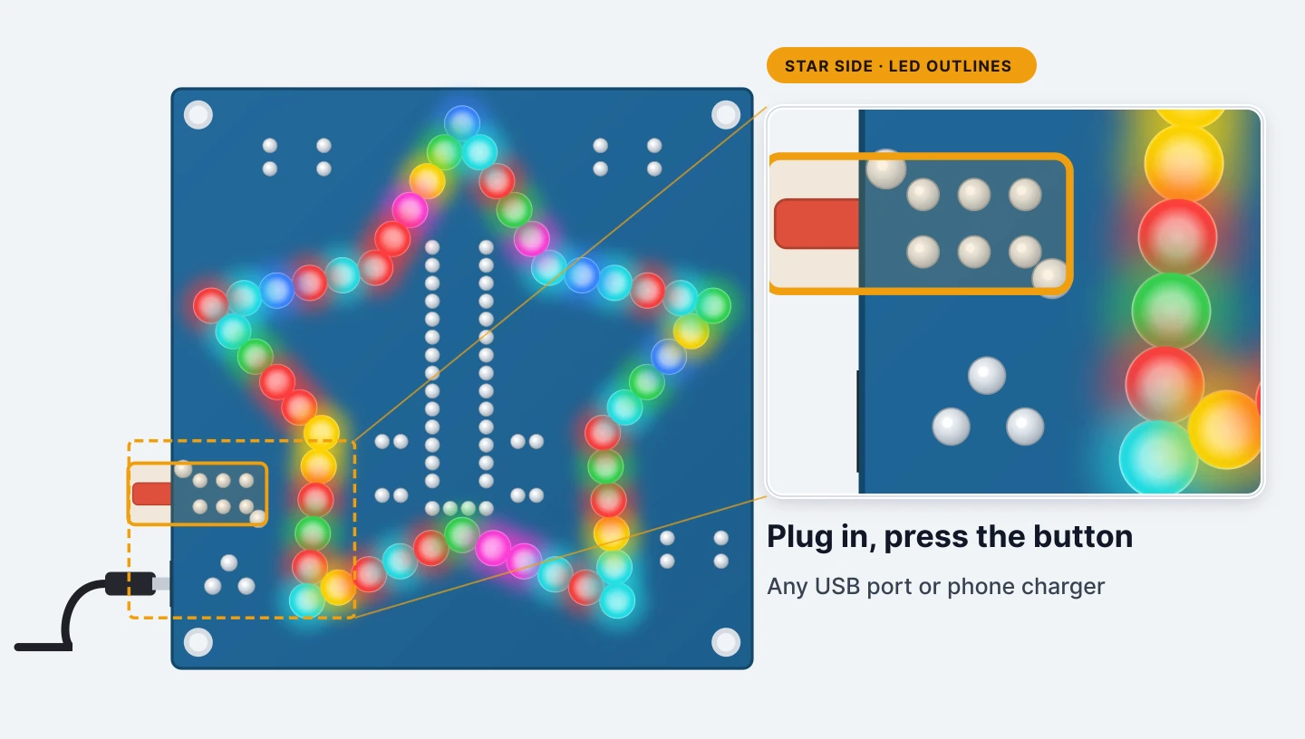
Plug the USB lead into the jack and a USB port or charger, and press the button. The whole star should come to life.
If some LEDs stay dark, the table in If it doesn’t work above narrows it down quickly.
Step 26 — Watch it run
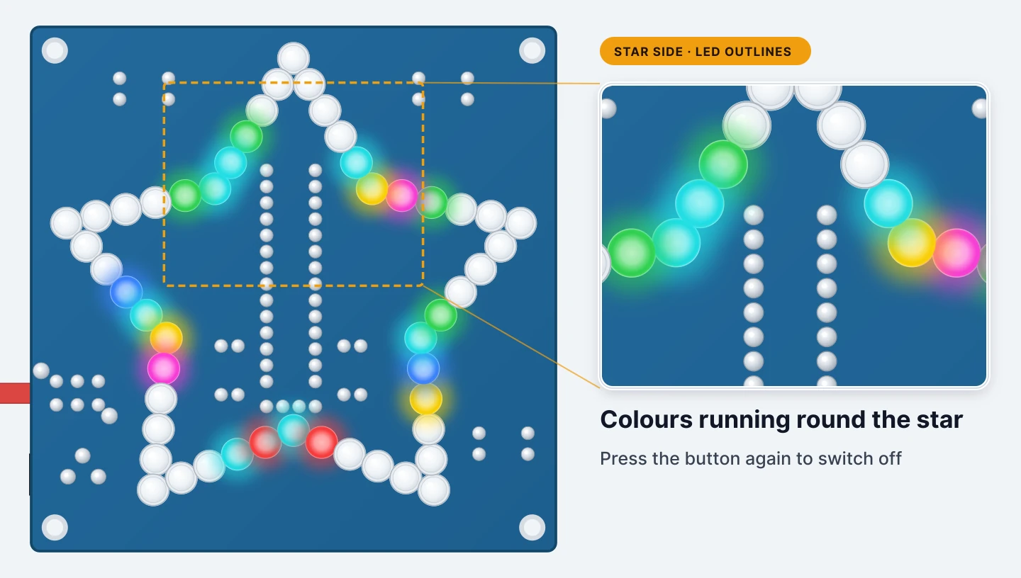
The chip steps through its patterns, switching LEDs on and off in pairs while each LED picks its own colour.
Press the button again to switch off. That’s the build finished. Nice work.
Step 27 — How the chip lights a pair
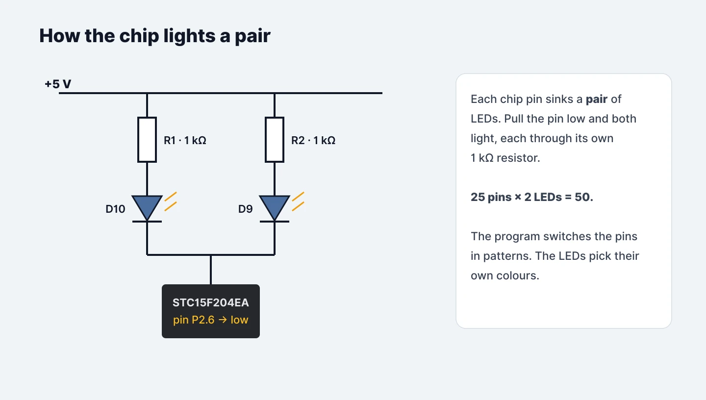
Each of the chip’s 25 output pins is wired to the negative legs of two LEDs. When the program pulls a pin low, both light, each through its own 1 kΩ resistor from +5 V.
The ten resistors are shared across all fifty LEDs. R1, for example, feeds D2, D4, D6, D8 and D10.
That’s why a dead resistor shows up as five scattered dark LEDs, while a bent chip pin darkens a single pair such as D9 and D10.
Step 28 — Going further: load your own program
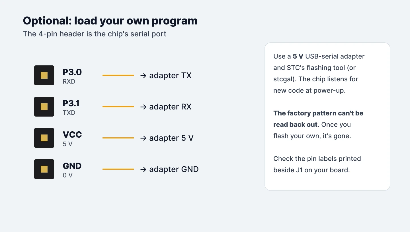
The STC15F204EA is a standard 8051-family microcontroller, and the 4-pin header (J1) is its serial port: P3.0 (RXD), P3.1 (TXD), VCC and GND. With a 5 V USB-serial adapter and STC’s ISP tool or the open-source stcgal, you can write your own patterns in C (for example with SDCC) and flash them. The chip checks for new code each time it powers up. Connect TX to RX and RX to TX, and check the pin labels printed beside J1 before you connect anything.
Be aware: STC chips can’t be read back, so once you flash your own program the factory light show is gone for good.
Pin map (from the kit’s schematic). Pull a pin low to light its pair: P2.6 → D9/D10, P2.7 → D7/D8, P1.0 → D5/D6, P1.1 → D3/D4, P1.2 → D1/D2, P1.3–P1.7 → D19/D20 down to D11/D12, P0.1 → D29/D30, P3.0–P3.3 → D27/D28 down to D21/D22, P3.4–P3.7 → D39/D40 down to D33/D34, P2.0 → D31/D32, P2.5–P2.1 → D49/D50 down to D41/D42.
Parts List
Required Parts (1)
Project Summary
1 part total
Unavailable items will be skipped
