
Beginner
Soldering the DIY Gas Detector
By Marcus Schappi
In this tutorial, youâll guide users through soldering the components of a DIY gas detector module. The kit likely includes a gas sensor MQ2, headers, resistors, and a PCB. The end goal is a functional sensor board that can detect gases such as CO, methane, or LPG
- DIY Gas Detector Kit (PCB + components)
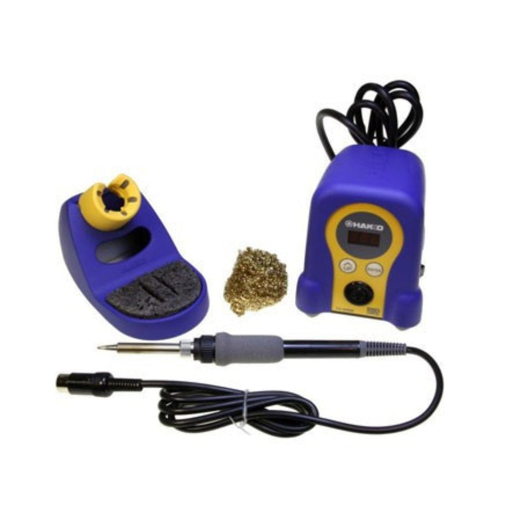
- Soldering iron (350°C recommended)
- Solder (lead-free)
- Soldering stand and cleaning sponge/brass tip cleaner
- Tweezers
- Diagonal cutters
- Fume extractor or good ventilation
Step 1 — Tools and Materials
- DIY Gas Detector Kit (PCB + components)
- Soldering iron (350°C recommended)
- Solder (lead-free)
- Soldering stand and cleaning sponge/brass tip cleaner
- Tweezers
- Diagonal cutters
- Fume extractor or good ventilation
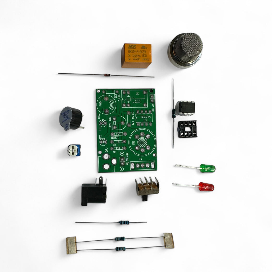
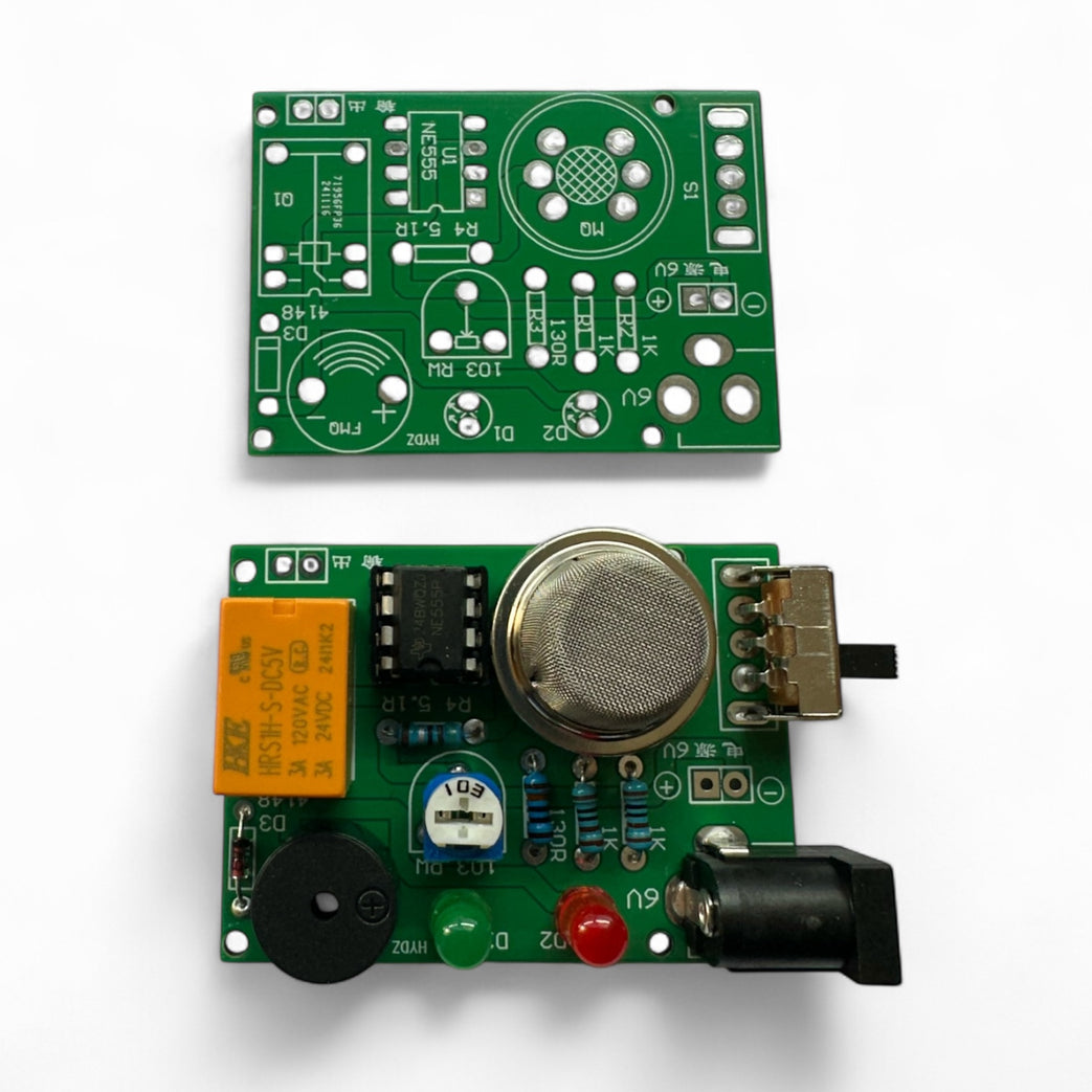
Step 2 — Kit Components
Component -
MQ2 Gas Sensor - Main sensor (large metal can)
PCB with Silkscreened with component layout
Buzzer for Sound alert
Potentiometer (Trimpot) - Sensitivity adjust
IC Socket + IC socket - NE555 comparator
Resistors x4
Rectifier Diode - Polarity protection
Green + Red LEDs - Status indicators
Orange Relay - For triggering external loads
Barrel Jack- Power input 6V Required
Switch - Power Control
Step 3 — Add Resistors
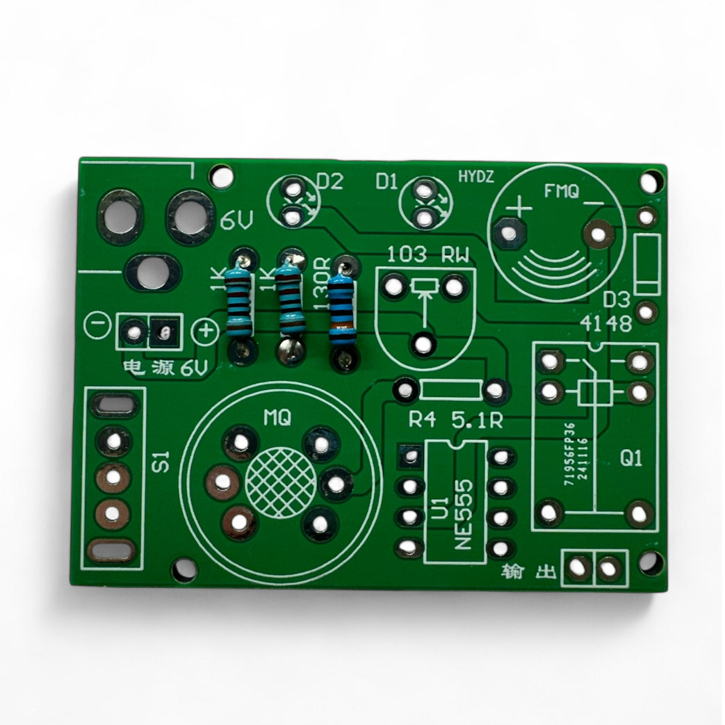
Insert Resistors (R1âR4)
Bend leads to fit the holes.
Bend leads to fit the holes.
Match resistor values according to the silkscreen.
R1 and R2 are 1K resistors -
- 1kΩ resistor colour code (4-band):
- Brown
- Black
- Red
- Gold
R3 is 130R
- Brown
- Orange
- Brown
- Gold
R4 is 5.1R
- Green
- Brown
- Gold
- Gold
Insert, flip the board, solder, and trim.
Step 4 — Add Trimpot (VR1), Buzzer and Power Jack
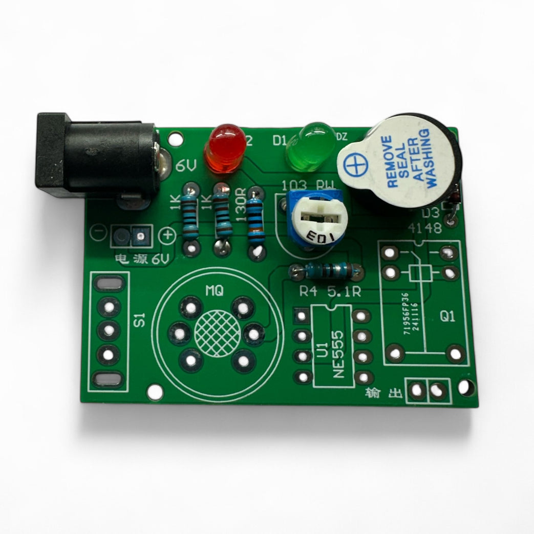
Add Trimpot (VR1)
- Used for threshold adjustment.
- Push in as far as it will go and solder.
Add the Buzzer (BZ1)
- Match polarity if marked (+ or â).
- Peel off the sticker and you will see a + on top.
- Push through, solder, and trim.
Add Power Jack (J1)
- These parts take more heatâuse flux if needed.
- Solder carefully so joints are solid.
Step 5 — Add Red and Green LED
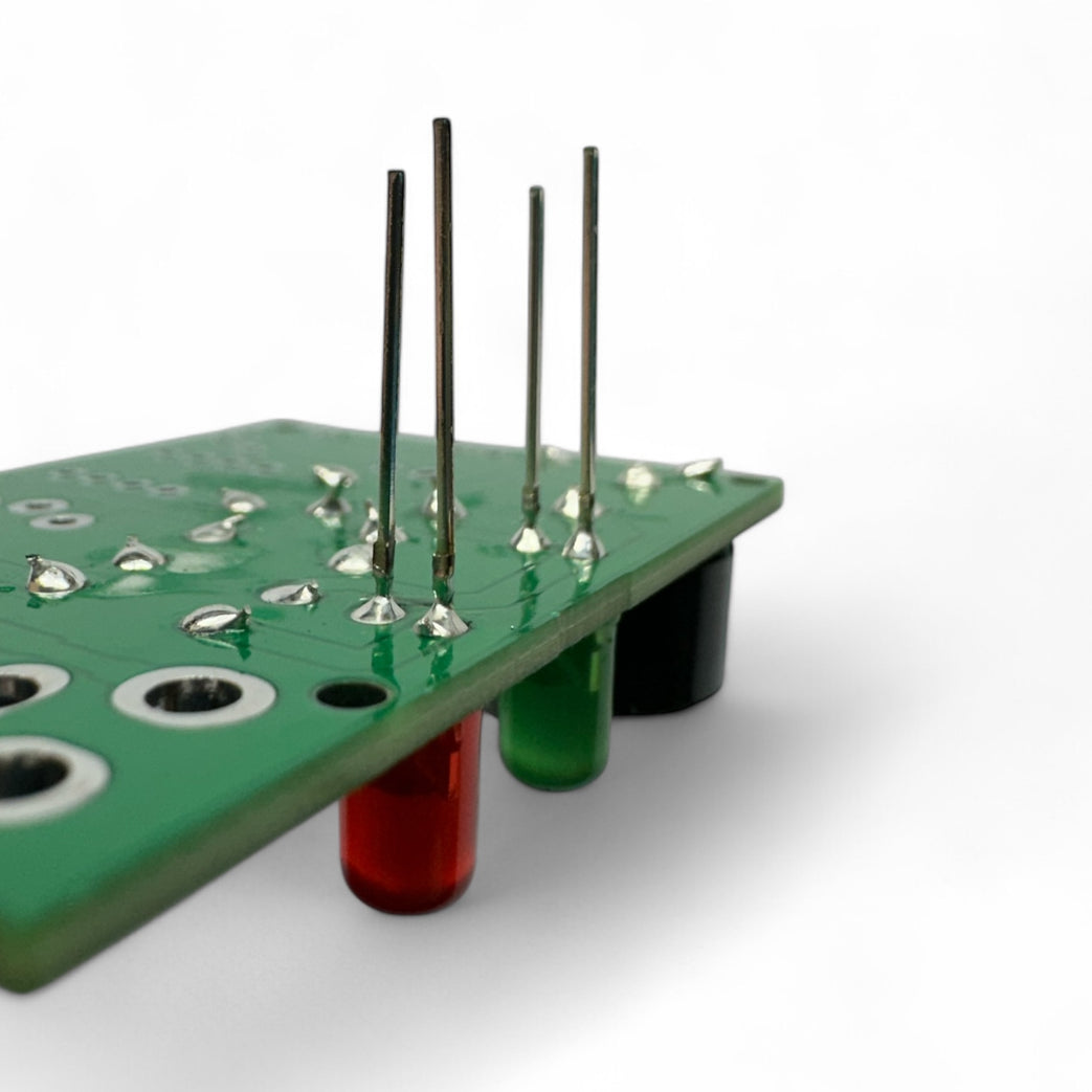
Solder the LEDs (D2 = Green, D3 = Red)
- Match the flat side (cathode) with the flat line on the PCB.
- The longer leg should be near the edge of the board.
- Test with a coin cell before soldering if unsure.
Step 6 — Step 6
Step 7 — Install the IC Socket
Install the IC Socket (U1)
- Align the notch in the socket with the notch on the PCB marking.
- Solder all 8 pins.
Insert the IC into the Socket
- Ensure orientation notch matches socket and silkscreen.
Step 8 — Power and Test
Power & Test
Supply 5Vâ9V via barrel jack
Sensor warms up (1â2 min)
Adjust the potentiometer until:
Green LED = baseline OK.
Red LED or buzzer = gas detected.
Test with a source of gas (e.g., lighter held near sensorânot lit!).
Supply 5Vâ9V via barrel jack
Sensor warms up (1â2 min)
Adjust the potentiometer until:
Green LED = baseline OK.
Red LED or buzzer = gas detected.
Test with a source of gas (e.g., lighter held near sensorânot lit!).
Parts List
Required Parts (1)
Optional Extras (4)


Project Summary
5 parts total
Required parts
$9.15
Optional extras
+$327.75
Total (required)
$9.15
Unavailable items will be skipped
