
Beginner
Pushbutton Module with Arduino
Detect button presses with the Arduino
By Cherie Tan
The Arduino Uno R3 has a reset button, but you can add more buttons to control other components, the built-in LED and more. In this guide, you will learn to connect an external push button to the Arduino, and get it to turn turn the built-in LED on and off. The push button module is comprised of a momentary push button switch and an in-built resistor. After completing this guide, you will know how to add more buttons to your Arduino.
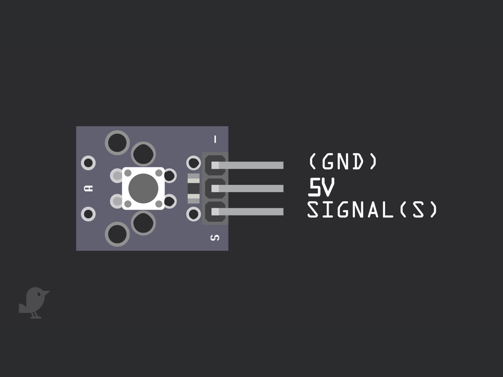
Before we put together the circuit, let's take a closer look at the Pushbutton Module. There are three pins here:
S : This is the signal pin which we will connect to a GPIO pin on the micro:bit
3.3V : Though it is unlabelled on the module, this middle pin will need to be connected to 3.3V on the micro:bit
GND: In electronics, we define a point in a circuit to be a kind of zero volts or 0V reference point, on which to base all other voltage measurements. This point is called ground or GND. Voltage is the difference in potential between two points. As it is difficult to talk about voltage without a reference point, we need another point to compare it to.
Step 1 — The Pushbutton Module
Before we put together the circuit, let's take a closer look at the Pushbutton Module. There are three pins here:
S : This is the signal pin which we will connect to a GPIO pin on the micro:bit
3.3V : Though it is unlabelled on the module, this middle pin will need to be connected to 3.3V on the micro:bit
GND: In electronics, we define a point in a circuit to be a kind of zero volts or 0V reference point, on which to base all other voltage measurements. This point is called ground or GND. Voltage is the difference in potential between two points. As it is difficult to talk about voltage without a reference point, we need another point to compare it to.
S : This is the signal pin which we will connect to a GPIO pin on the micro:bit
3.3V : Though it is unlabelled on the module, this middle pin will need to be connected to 3.3V on the micro:bit
GND: In electronics, we define a point in a circuit to be a kind of zero volts or 0V reference point, on which to base all other voltage measurements. This point is called ground or GND. Voltage is the difference in potential between two points. As it is difficult to talk about voltage without a reference point, we need another point to compare it to.
Step 2 — Connect GND to GND
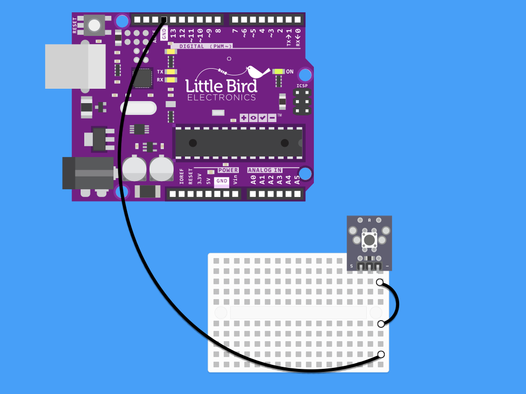
Connect a black jumper wire from - on the button module to GND on the Arduino
Step 3 — Connect 5V to the Middle Pin
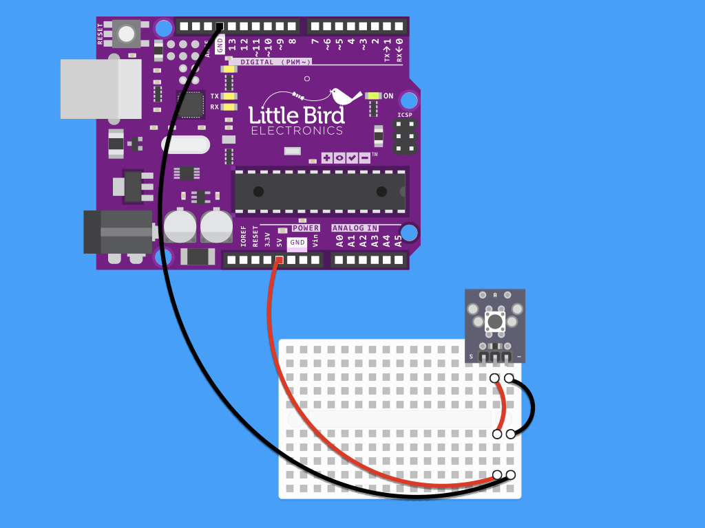
Next, connect a red jumper wire from the middle pin of the button module to 5V on the Arduino
Step 4 — Connect SIG to Digital Pin 3
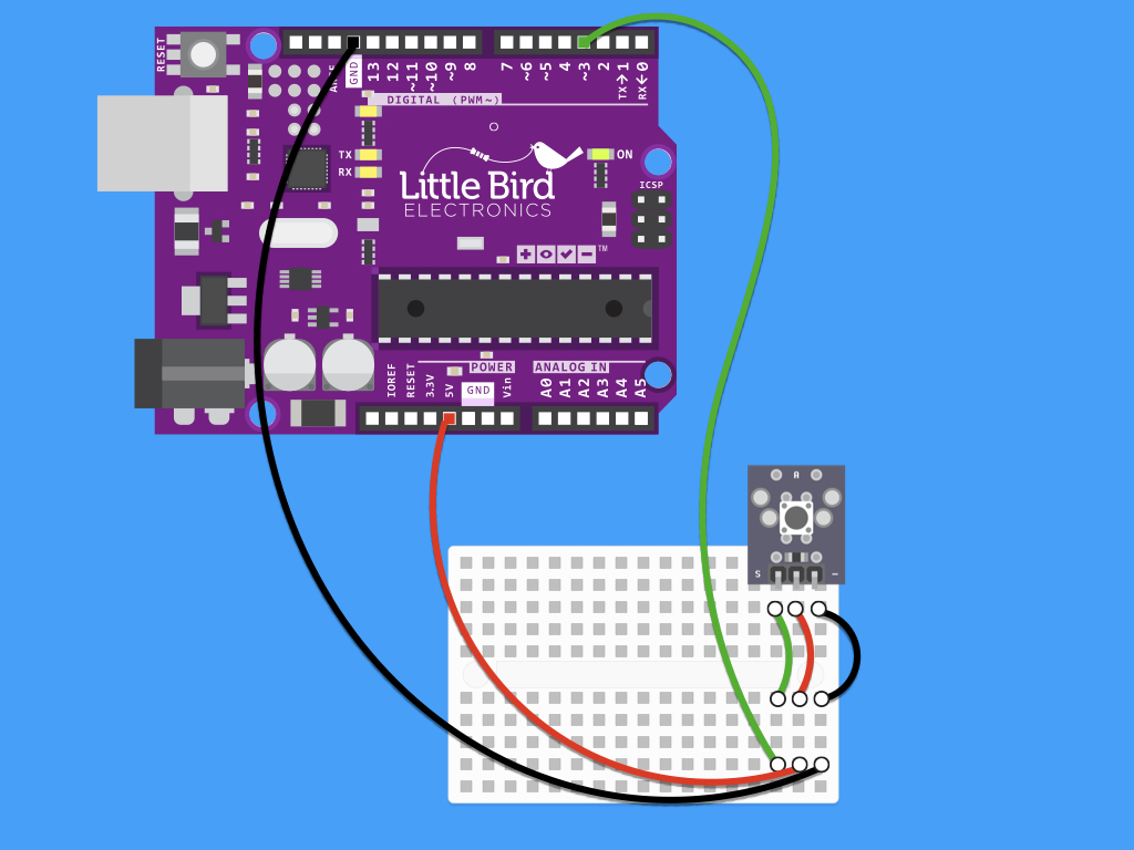
Now connect a jumper wire from the signal pin, labelled "S" on the button module to Digital Pin 3 on the Arduino
