
Intermediate
Macro Keypad with ATmega32u4
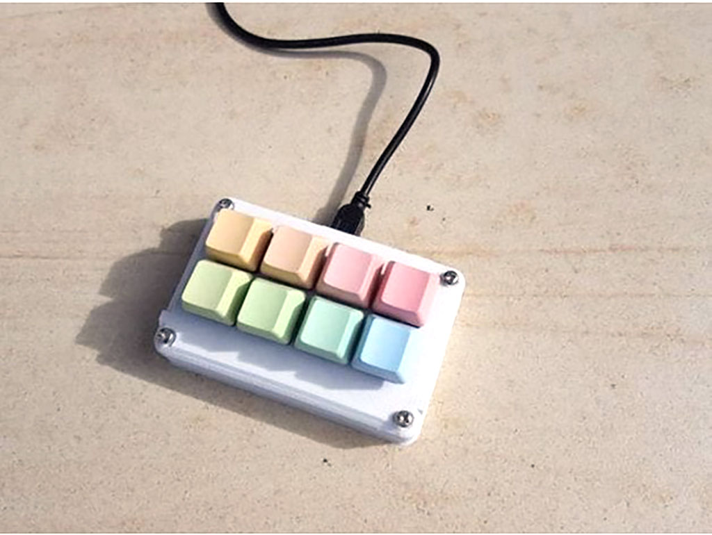
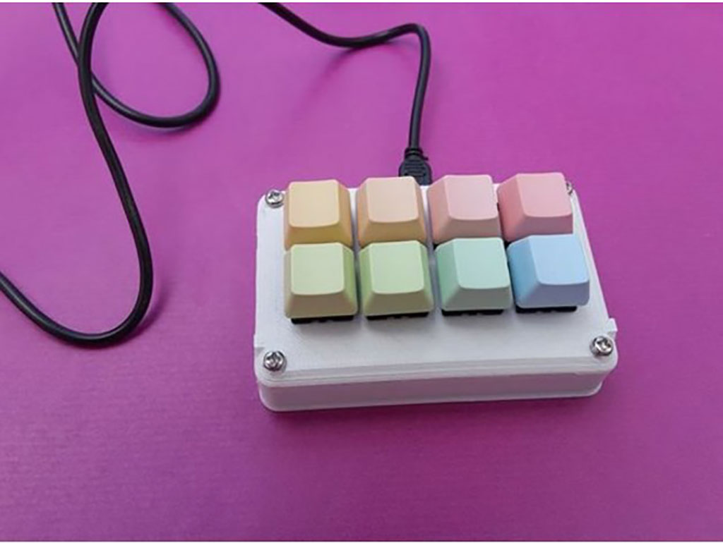
Create your own programmable eight button macro keypad!
By Cherie Tan
The ATmega32u4 found on the Teensy board is capable of emulating a USB HID device such as a keyboard or mouse.
In this guide, learn to use the Bounce.h library to emulate a USB HID device.
Complete this guide to create your own programmable eight-button macro keypad.
In this guide, learn to use the Bounce.h library to emulate a USB HID device.
Complete this guide to create your own programmable eight-button macro keypad.
The ATmega32u4 found on the Teensy board is capable of emulating a USB HID device such as a keyboard or mouse. In this guide, we'll show you how to create your own programmable macro keypad with the Teensy, Cherry MX Red Switches, a handful of jumper wires, and a custom 3D printed case.
Got an Arduino Pro Micro lying around? The Arduino Pro Micro also has an ATmega32u4, with a full-speed uSB transceiver, so you may also use it to create a macro keypad!
Step 1 — Overview
The ATmega32u4 found on the Teensy board is capable of emulating a USB HID device such as a keyboard or mouse. In this guide, we'll show you how to create your own programmable macro keypad with the Teensy, Cherry MX Red Switches, a handful of jumper wires, and a custom 3D printed case.
Got an Arduino Pro Micro lying around? The Arduino Pro Micro also has an ATmega32u4, with a full-speed uSB transceiver, so you may also use it to create a macro keypad!
Step 2 — 3D Printed Case: 8-Button Variation
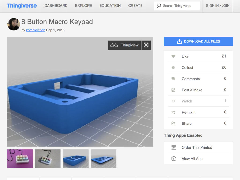
First, head to Thingiverse to download the STL files for the 8-button macro keypad case.
There are two parts to the case. Printing it in either PLA or ABS will both work fine.
Step 3 — Connect black jumper wires along Row #1

After placing the eight Cherry Red MX switches into the front panel of the case, solder jumper wires along the first row of switches.
It won't matter which leg of a switch is used, but to keep it looking a little more organised, solder wires along the legs that are on the same side.
Step 4 — Connect black jumper wires along Row #2
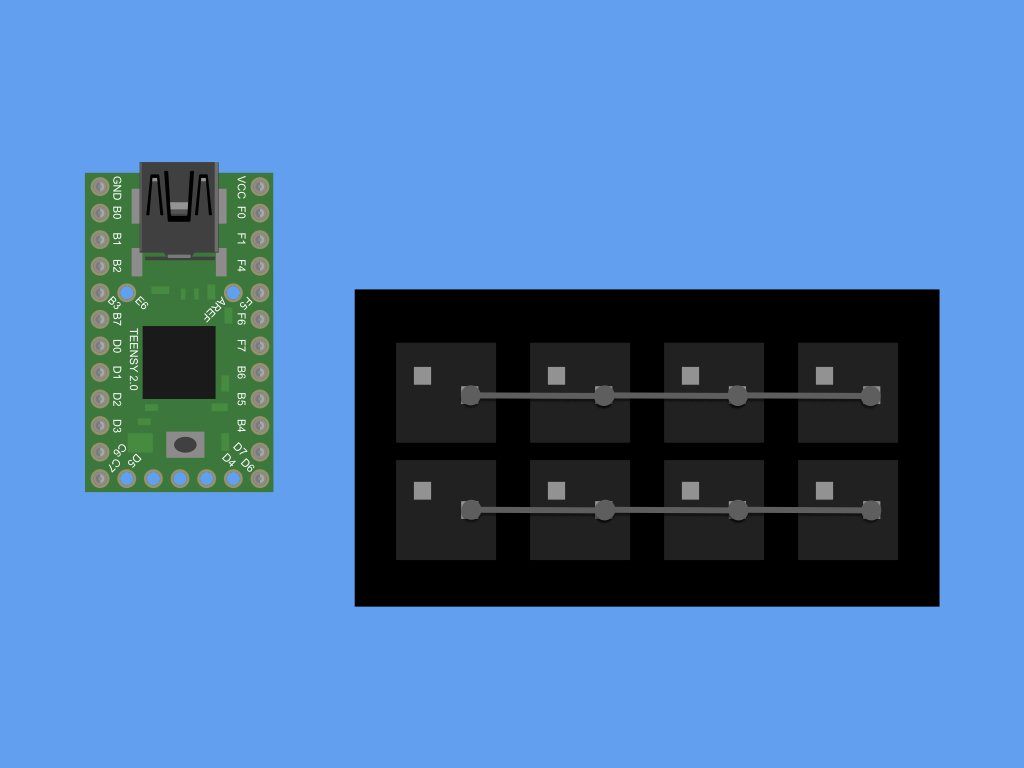
Solder jumper wires along the second row of switches.
Step 5 — Connect GND on both rows

Solder a jumper wire, connecting the first row of soldered pins to the second row.
Step 6 — Connect to GND on Teensy

Now solder a wire from the two rows to GND on the Teensy board.
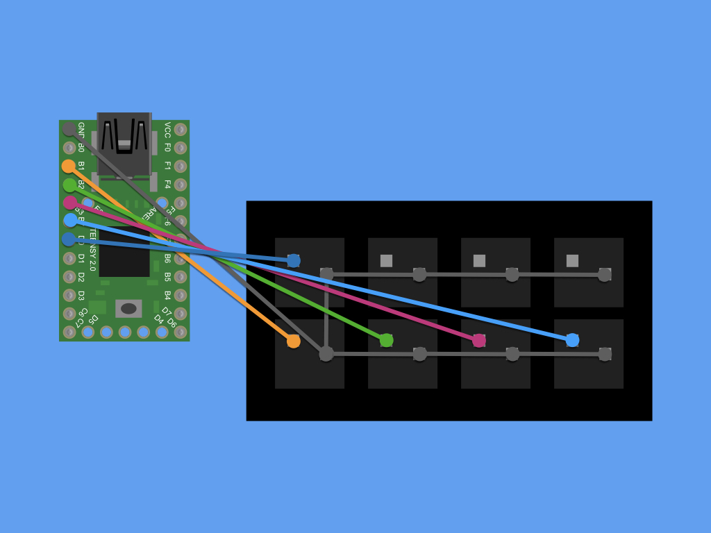
Step 7 — Connect to B1

Connect a switch to B1 on the Teensy.
Step 8 — Connect to B2

Connect a switch to B2 on the Teensy.
Step 9 — Connect to B3
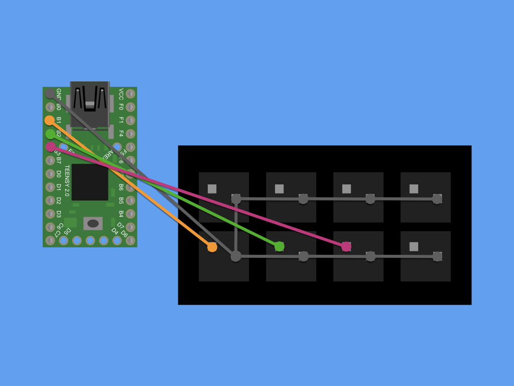
Connect a switch to B3 on the Teensy.
Step 10 — Connect to B7

Connect a switch to B7 on the Teensy.
Step 11 — Connect to D0
Connect a switch to D0 on the Teensy.
Step 12 — Connect to D1

Connect a switch to D1 on the Teensy.
Step 13 — Connect to F1
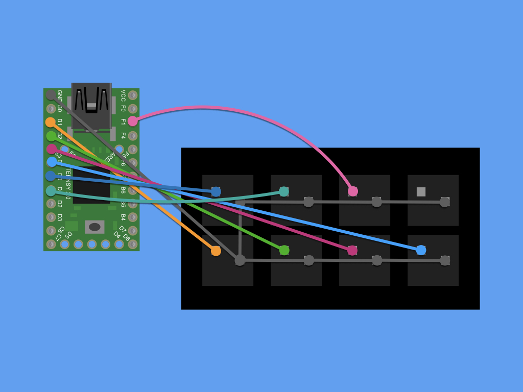
Connect a switch to F1 on the Teensy.
Step 14 — Connect to F4
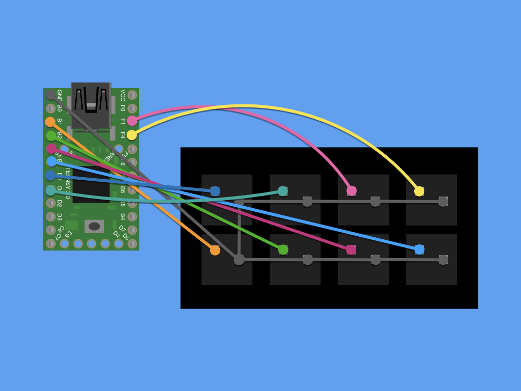
Connect a switch to F4 on the Teensy.
Step 15 — Teensyduino setup
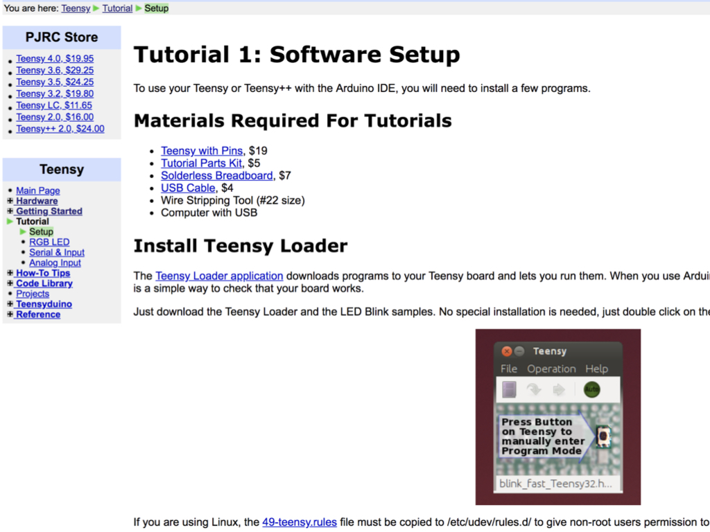
Before we can upload a sketch to the Teensy board, a few programs will need to be installed such as the Teensy Loader application. Follow the instructions here.
Step 16 — Combine the 3D printed parts
Combine the front panel and bottom part of the case together with four phillips head screws.
Connect a mini USB cable to the Teensy, and connect its USB end to the computer.
Step 17 — Sketch
/* Buttons to USB Keyboard Example
   You must select Keyboard from the "Tools > USB Type" menu
   This example code is in the public domain.
*/

#include <Bounce.h>

// Create Bounce objects for each button.  The Bounce object
// automatically deals with contact chatter or "bounce", and
// it makes detecting changes very simple.
Bounce button0 = Bounce(1, 50);
Bounce button1 = Bounce(2, 50);  // 10 = 10 ms debounce time
Bounce button2 = Bounce(3, 50);  // which is appropriate for
Bounce button3 = Bounce(4, 50);  // most mechanical pushbuttons
Bounce button4 = Bounce(5, 50);
Bounce button5 = Bounce(6, 50);  // if a button is too "sensitive"
Bounce button6 = Bounce(20, 50);  // to rapid touch, you can
Bounce button7 = Bounce(21, 50);  // increase this time.


void setup() {
  // Configure the pins for input mode with pullup resistors.
  // The pushbuttons connect from each pin to ground.  When
  // the button is pressed, the pin reads LOW because the button
  // shorts it to ground.  When released, the pin reads HIGH
  // because the pullup resistor connects to +5 volts inside
  // the chip.  LOW for "on", and HIGH for "off" may seem
  // backwards, but using the on-chip pullup resistors is very
  // convenient.  The scheme is called "active low", and it's
  // very commonly used in electronics... so much that the chip
  // has built-in pullup resistors!
  pinMode(1, INPUT_PULLUP);
  pinMode(2, INPUT_PULLUP);
  pinMode(3, INPUT_PULLUP);
  pinMode(4, INPUT_PULLUP);
  pinMode(5, INPUT_PULLUP);
  pinMode(6, INPUT_PULLUP);
  pinMode(20, INPUT_PULLUP);  // Teensy++ LED, may need 1k resistor pullup
  pinMode(21, INPUT_PULLUP);
}

void loop() {
  // Update all the buttons.  There should not be any long
  // delays in loop(), so this runs repetitively at a rate
  // faster than the buttons could be pressed and released.
  button0.update();
  button1.update();
  button2.update();
  button3.update();
  button4.update();
  button5.update();
  button6.update();
  button7.update();

  // Check each button for "falling" edge.
  // Type a message on the Keyboard when each button presses
  // Update the Joystick buttons only upon changes.
  // falling = high (not pressed - voltage from pullup resistor)
  //           to low (pressed - button connects pin to ground)
  if (button0.fallingEdge()) {
    //Set button 0  to
    Keyboard.press(KEY_LEFT_CTRL);
    Keyboard.press(KEY_D);
    delay(100);
    Keyboard.releaseAll();
  }
  if (button1.fallingEdge()) {
    Keyboard.press(KEY_LEFT_CTRL);
    Keyboard.press(MODIFIERKEY_RIGHT_SHIFT);
    Keyboard.press(KEY_EQUAL);
    delay(100);
    Keyboard.releaseAll();
  }
  if (button2.fallingEdge()) {
     //Set button 2 to
    Keyboard.press(KEY_LEFT_CTRL);
    Keyboard.press(KEYPAD_0);
    delay(100);
    Keyboard.releaseAll();
  }
  if (button3.fallingEdge()) {
    //Set button 3 to
    Keyboard.press(KEY_END);
    delay(100);
    Keyboard.releaseAll();
  }
  if (button4.fallingEdge()) {
    Keyboard.press(KEY_LEFT_CTRL);
    Keyboard.press(KEY_Z);
    delay(100);
    Keyboard.releaseAll();
  }
  if (button5.fallingEdge()) {
    Keyboard.press(MODIFIERKEY_RIGHT_SHIFT);
    Keyboard.press(KEYPAD_5);
    delay(100);
    Keyboard.releaseAll();
  }
    if (button6.fallingEdge()) {
    Keyboard.press(KEY_PAGE_UP);
    delay(100);
    Keyboard.releaseAll();
  }
    if (button7.fallingEdge()) {
    Keyboard.press(KEY_PAGE_DOWN);
    delay(100);
    Keyboard.releaseAll();
  }
}
Copy and paste the following code into the Arduino IDE.
Make sure Tools > USB Type is selected.
Click on the Verify button.
Click on the Upload button.
When called, Keyboard.press() functions as if a key were pressed and held on your keyboard.
Keyboard.releaseAll() lets go of all keys currently pressed.
Keyboard.releaseAll() lets go of all keys currently pressed.
You may not want a button to be programmed as say LEFT_CTRL + Z. For a complete table of Key Codes, see here.
Step 18 — Conclusion
Your build is now complete. As a next step, you may want to create one with more buttons, check out the 16 button variation on Thingiverse.
