
Beginner
Light Dependent Resistor Module with Arduino
Sense light with your Arduino and this module
By Cherie Tan
Light-dependent resistors, also known as photo-resistors, are sensors that allow the detection of light. They are not only useful but are small and inexpensive. In this guide, you will learn to use a light-dependent resistor module with the Arduino. We will use a Little Bird Uno R3 board, a mini breadboard, some jumper wires, and the module. You will learn to hook it up to the Arduino board, and measure the relative brightness of the environment.
Let's take a closer look at the light-dependent resistor module as well as the buzzer module. The light-dependent resistor module has four pins: 3.3V : While 'VCC' stands for Voltage Common Collector, we'll connect the VCC pin to 3.3V on the micro:bit GND: In electronics, we define a point in a circuit to be a kind of zero volts or 0V reference point, on which to base all other voltage measurements. This point is called ground or GND. Note: Voltage is the difference in potential between two points. As it is difficult to talk about voltage without a reference point, we need another point to compare it to. DO: Digital Output AO: Analog Output
Step 1 — The Light Dependent Resistor Module
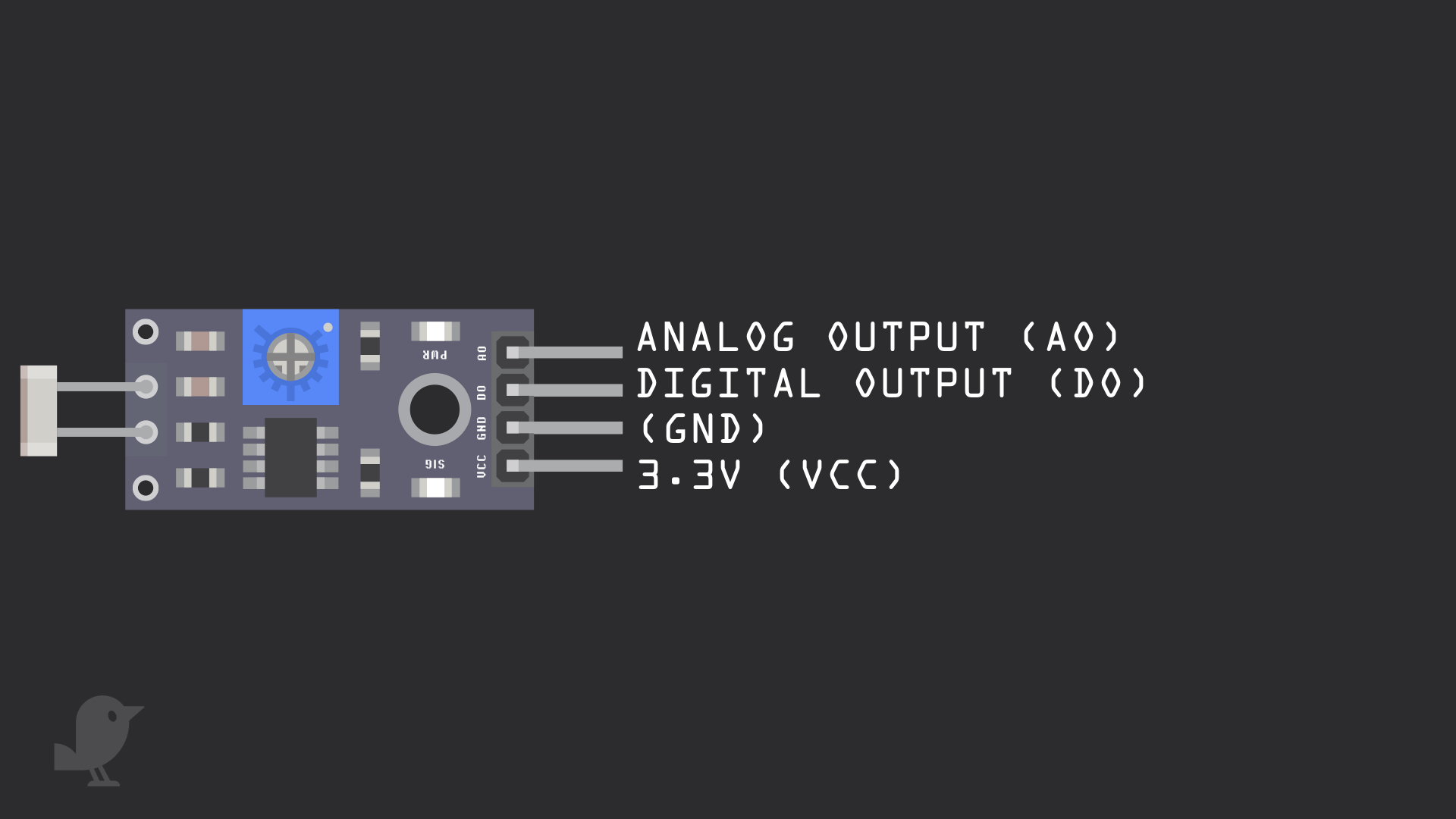
Let's take a closer look at the light-dependent resistor module as well as the buzzer module. The light-dependent resistor module has four pins: 3.3V : While 'VCC' stands for Voltage Common Collector, we'll connect the VCC pin to 3.3V on the micro:bit GND: In electronics, we define a point in a circuit to be a kind of zero volts or 0V reference point, on which to base all other voltage measurements. This point is called ground or GND. Note: Voltage is the difference in potential between two points. As it is difficult to talk about voltage without a reference point, we need another point to compare it to. DO: Digital Output AO: Analog Output
Step 2 — Connect LDR module to breadboard

Connect the light dependent resistor onto the breadboard.
Step 3 — Connect + to VCC
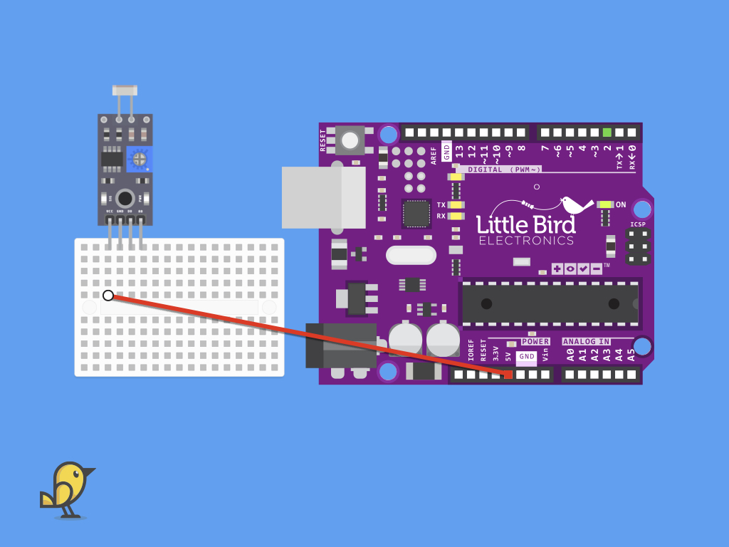
Plug one end of a jumper wire to the breadboard as shown. Connect the other end to the light dependent resistor module.
Step 4 — Connect GND to GND
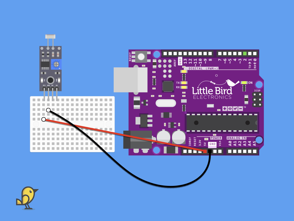
Connect a black jumper wire from GND of the module to GND on the Little Bird Uno R3
Step 5 — Connect AO to A0
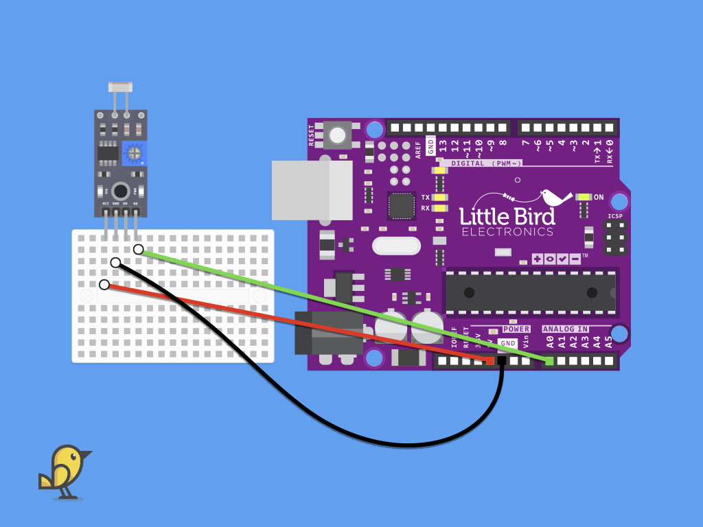
Next, connect the analog output pin (AO) of the module to A0 pin on the Little Bird Uno R3
Step 6 — Code for Light dependent resistor module
void setup() {
  Serial.begin(9600); //initialise serial monitor

}

void loop() {
  unsigned int lightVal;
  int lightVal=analogRead(A0);  //assign value of LDR sensor to a temporary variable
  Serial.println("Intensity=");
  Serial.println(lightVal);     //display output on serial monitor
}
Upload this code to your Little Bird Uno R3 This program will read the analog value from the module. The resistance of a light dependent resistor varies by how much light is falling on it. Around bright light, this value will be different to being in complete darkness. Cover the module with a hand and watch what happens to the values shown in the serial monitor! Then expose the module to sunlight and watch the value change again.
