
Beginner
Laser Sensor for Arduino
Create a simple tripwire alarm
By Cherie Tan
Ever seen grids of laser beams protecting valuables? Then you've probably seen a laser sensor module at work. The laser beams may seem high-tech, but the principles behind them are simple.
In this guide, you will get familiar with the laser sensor module and use it with an Arduino to create a simple tripwire alarm system. It will let you know if anyone is sneaking about!
After completing this guide, you will understand how to use a laser sensor module and can go on to create projects of your own!
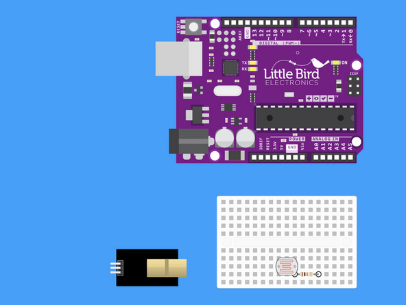
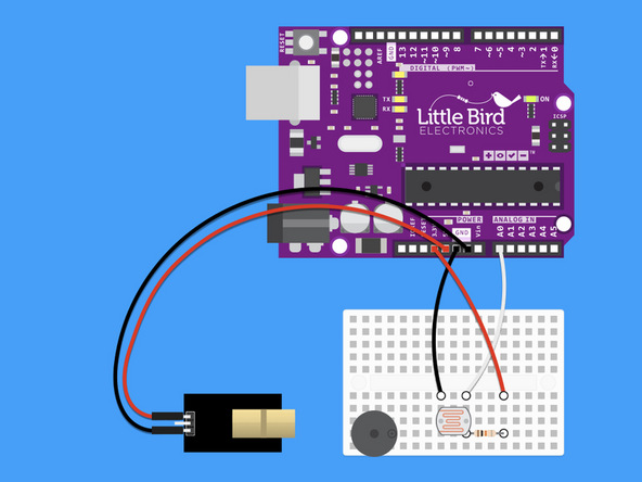
Insert your LDR into your Breadboard.
The LDR is not polarised so the orientation of the LDR doesn't matter. Just be sure that the legs are not in the same row. (Note our breadboard is rotated 90º).
Step 1 — Insert your LDR into your Breadboard

Insert your LDR into your Breadboard.
The LDR is not polarised so the orientation of the LDR doesn't matter. Just be sure that the legs are not in the same row. (Note our breadboard is rotated 90º).
Step 2 — Insert your 10k Ohm Resistor
Insert your 10k Ohm resistor such that one of the resistor's legs shares a row with one of the legs of the LDR.
Your 10k Ohm resistor has the colour bands: "Brown, Black, Black, Red, Brown".
Step 3 — Connect the LDR to Ground

From the row with just the LDR leg put the black jumper wire and run it to GND (ground).
Step 4 — Connect a jumper from A0 to the Voltage Divider Output

From the row where the legs share, use your white jumper wire and insert it into your Arduino's Analogue 0 Pin.
Step 5 — Connect 3.3V to the 10k Ohm Resistor
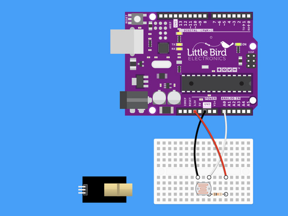
Run a red jumper wire from your Arduino's 3V pin to the other leg of your 10k resistor.
Step 6 — Connect 5V to the Laser Module
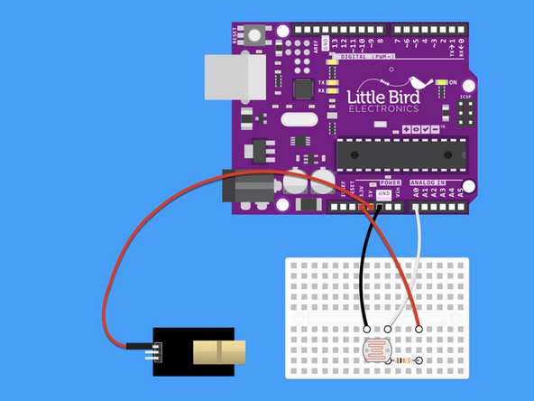
Run a red jumper wire from your Arduino's 5V pin to the S leg of the Laser Module.
Step 7 — Connect the Laser Module to Ground
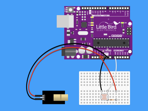
Connect the '-' pin to an Arduino ground pin.
Step 8 — Plug your buzzer in
Plug your Buzzer in so that the positive pin is on the right hand side.
There are markings on the buzzer which indicate the positive and negative pins.
Step 9 — Connect the Digital Pin 9 to the Buzzer
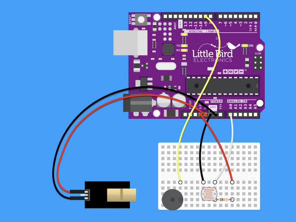
Connect the Digital Pin 9 to the Buzzer's positive pin.
Step 10 — Connect the Buzzer to the Ground
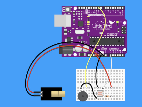
Connect the Buzzer's negative pin to ground.
Step 11 — Upload the code
int ldr = 0; //analog pin to which LDR is connected
int ldr_value = 0; //variable to store LDR values
const int buzzer = 9;

void setup() {
  Serial.begin(9600); //start the serial monitor
}

void loop() {
  ldr_value = analogRead(ldr); //reads the LDR values
  Serial.println(ldr_value); //prints the LDR values to serial monitor
  delay(100); //wait

  if (ldr_value < 600) {
    tone(buzzer, 1000);
    delay(3000); // 3 seconds of beeping to tell you the trip wire has been broken
  } else {
    noTone(buzzer);
  }

}
Upload this code - now when the laser gets broken the buzzer will go for 3 seconds!
Step 12 — The trip wire in action
Watch the complete trip wire in action!
Parts List
Optional Extras (2)

Project Summary
2 parts total
Required parts
$0.00
Optional extras
+$25.80
Total (required)
$0.00
Unavailable items will be skipped
