SparkFun
SparkFun QwiicBus Kit
The SparkFun QwiicBus Kit comes with everything you need to get started with the SparkFun QwiicBus system in one handy package. The kit includes two QwiicBus...
Get notified when back in stock
The SparkFun QwiicBus Kit comes with everything you need to get started with the SparkFun QwiicBus system in one handy package. The kit includes two QwiicBus EndPoints, one MidPoint and two 3ft Ethernet cables.
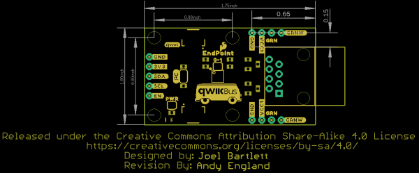
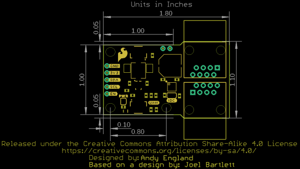
The SparkFun QwiicBus EndPoint is the fastest and easiest way to extend the range of your I2C communication bus. Both boards use NXP’s PCA9615 IC, which converts the two default I2C signals into four differential signals, two for SCL and two for SDA. The differential signals are sent over an Ethernet cable, which attaches to the breakout through the on-board RJ-45 connectors The differential signaling allows the I2C signals to reach distances of up to 100ft. while still maintaining their signal integrity! To make it even easier to get your readings, all communication is enacted exclusively via I2C, utilizing our handy Qwiic system so no soldering is required to connect it to the rest of your system. However, we still have broken out 0.1"-spaced pins in case you prefer to use a breadboard.
The QwiicBus MidPoint works in tandem with the QwiicBus Endpoint so you can easily tap into it to drop in devices wherever you would like.
The SparkFun Qwiic Connect System is an ecosystem of I2C sensors, actuators, shields and cables that make prototyping faster and less prone to error. All Qwiic-enabled boards use a common 1mm pitch, 4-pin JST connector. This reduces the amount of required PCB space, and polarized connections mean you can’t hook it up wrong.
Includes:
Documents:
QwiicBus General Documentation
- Hookup Guide
- Datasheet (PCA9615)
- Qwiic Info Page
QwiicBus EndPoint Documentation
QwiicBus MidPoint Documentation
Videos
Jargon buster
Plain-language definitions for the technical terms used above.
- breakout
- A breakout board carries a small or fine-pitched component and brings its connections out to standard, breadboard- and header-friendly pins. Describing a part as a breakout means it can be wired into a project without soldering directly to the component's tiny contacts.
- PCB
- A printed circuit board (PCB) is a board, usually rigid, with etched copper tracks that connect electronic components together without loose wiring. Components are mounted on the board and signals route between them through the copper layout.
- Qwiic
- Qwiic is a plug-in connector system for I2C devices that uses small 4-pin cables, so you can connect compatible sensors without soldering. It matters because your controller or adapter also needs Qwiic, or you will need a cable or breakout to wire it up.
Find this product in
STEM & Education
PCA9615 Datasheet
Datasheet · 899.7 KB · Click any page to view full size
QwiicBus Endpoint Schematic
Schematic · 126.7 KB · Click any page to view full size
QwiicBus Midpoint Schematic
Schematic · 129.0 KB · Click any page to view full size
LMR33630 Datasheet
Datasheet · 4.1 MB · Click any page to view full size
Supplier page — sparkfun.com
Supplier Description · 498.8 KB · Click any page to view full size
Resources & Downloads
Guides, code examples, and more
Source Code
Open-source libraries, firmware & example projects for this product
Extend your I2C communication bus with the Qwiic Long Distance board.
4960031
about 8 years ago
· 12 commits
- Documentation ENG Checklist update over 8 years ago
- Hardware Ready for REDs over 8 years ago
- Production panel over 8 years ago
- .gitignore Initial commit over 8 years ago
- LICENSE.md Initial commit of .brd and .sch files over 8 years ago
- README.md Update README.md about 8 years ago
4a813ba
over 5 years ago
· 4 commits
- Hardware removing backup files adding gitignore over 5 years ago
- Production RE-panelization for stronger inner-support tabs over 5 years ago
- .gitignore removing backup files adding gitignore over 5 years ago
- README.md Create README.md over 5 years ago
Related Tutorials
Free guides on learn.littlebird.com.au

