
Intermediate
Automatic Plant Watering with Arduino
Learn to set up an automatic plant watering system with the Arduino
By Cherie Tan
Want to keep your plants watered while away on vacation? Build your own automatic plant-watering system using our Automatic Plant Watering Kit and an Arduino.
In this guide, learn to connect the kit to the Arduino or as a standalone, then program it to monitor soil moisture levels. When the soil moisture level goes below the set threshold, the plant will be automatically watered.
Complete this guide to get started with building your own automatic plant watering system!
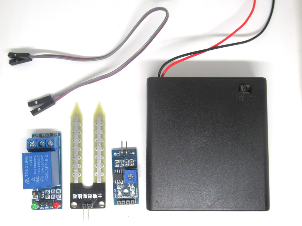
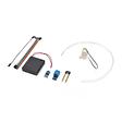
Our Auto Plant Watering kit comes with:
- 5V Relay Module
- Soil moisture probes + comparison module
- Small submersible pump
- 50cm tube
- Battery pack enclosure
- USB power line
- Jumper wires
It can be used as a standalone, or together with the Arduino.
Please jump to Step 16 if you would like to connect the components as a standalone.
Step 1 — The Kit
Our Auto Plant Watering kit comes with:
- 5V Relay Module
- Soil moisture probes + comparison module
- Small submersible pump
- 50cm tube
- Battery pack enclosure
- USB power line
- Jumper wires
It can be used as a standalone, or together with the Arduino.
Please jump to Step 16 if you would like to connect the components as a standalone.
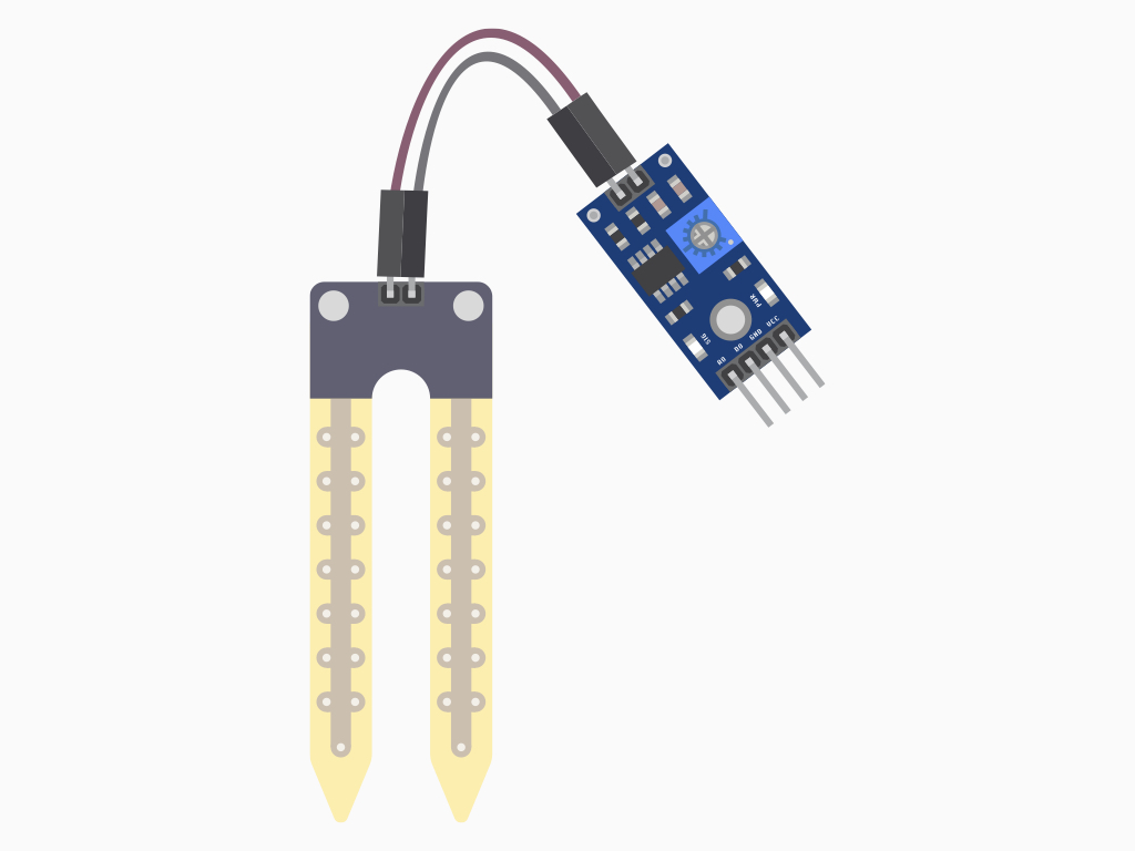
Step 2 — Soil Moisture Sensor
The water content in surrounding air and materials such as soil is an important factor for the well-being of humans, animals, plants, and other living things. The term moisture generally refers to the water content of any material. It is applied to liquids and solids, whereas humidity refers to the water vapor content in gases.
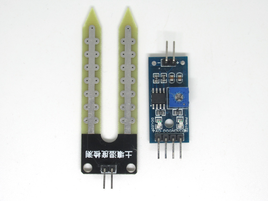
This soil moisture sensor in our kit has two probes to pass current through the soil. It measures the resistance and represents the change in resistance as moisture level. More water makes the soil conduct electricity more easily (less resistance), while dry soil conducts electricity poorly (more resistance). This sensor will be helpful as a reminder to water your indoor plants or to monitor the soil moisture in your garden.
A closer look at the pins: There are two pins on the soil moisture sensor, these connect to the two other pins on the top of the module as shown in Step 7.
There are four pins on the module:
AO: Analog Output
DO: Digital Output
VCC: 'VCC' stands for Voltage Common Collector. We'll connect the VCC pin to 5V on the Arduino
GND: In electronics, we define a point in a circuit to be a kind of zero volts or 0V reference point, on which to base all other voltage measurements. This point is called ground or GND.
Voltage is the difference in potential between two points. As it is difficult to talk about voltage without a reference point, we need another point to compare it to.
Step 3 — The 5V Relay Module
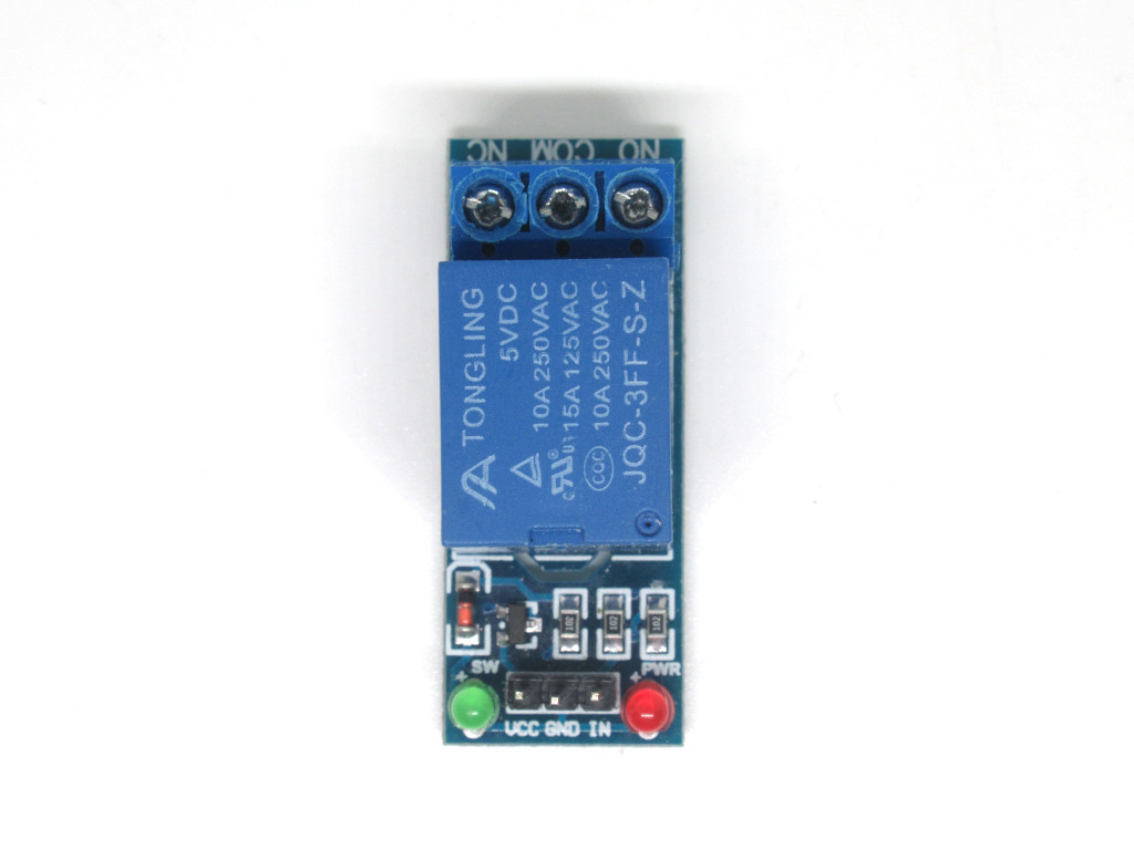
The next component in the kit we'll take a closer look at is the 5V relay module. Instead of using a relay and wiring it up with transistors, diodes and resistors or any other additional components, a relay module board like this already includes everything you need.
What is a relay? A relay is basically an electrically actuated switch. Many sensors are incredibly sensitive and which may produce only small electric currents. When we need to use them in circuits involving larger currents, that's when relays bridge the gap; A relay makes it possible for small currents to activate larger ones, and to safely do so.
In this guide, the relay is used to turn the submersible water pump on and off.
Three of its pins control the state of the relay:
VCC: In this guide, we connected it to 5V
GND: Connected to GND.
Input (IN): This is the signal connection that is used to control the relay.
VCC: In this guide, we connected it to 5V
GND: Connected to GND.
Input (IN): This is the signal connection that is used to control the relay.
Three of the other connections control the circuit:
NC - Stands for 'Normally closed'. it is connected to COM when there is a trigger in the relay.
NO - Stands for 'Normally open'. It is normally connected to COM when there is no trigger in the relay.
COM - Stands for 'Common'. it is the part of the relay that moves.
When a relay is off, COM is connected to NC. When the relay turns on, it moves from NC to NO
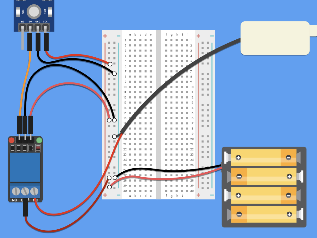
Step 4 — Connect VCC to 5V
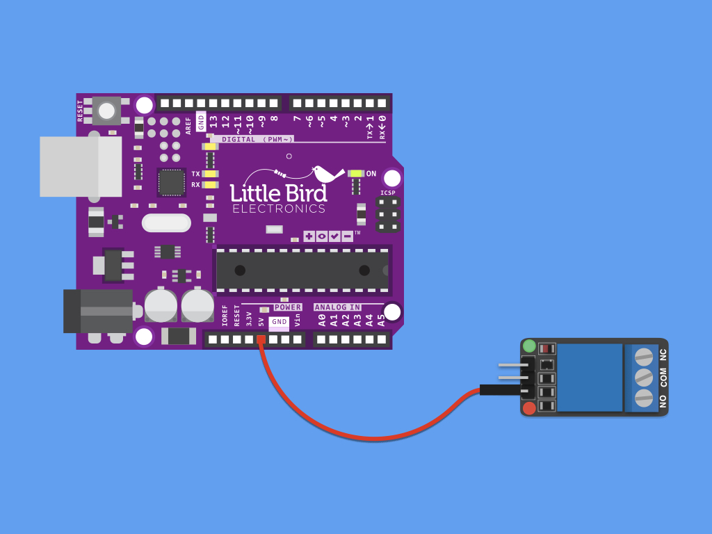
Without further ado, let's get started with connecting up the components.First, connect VCC on the relay to 5V pin on Arduino
Step 5 — Connect GND to negative power rail
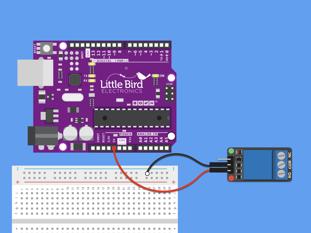
Connect GND on the relay to negative power rail of breadboard
Step 6 — Connect IN to Pin 3
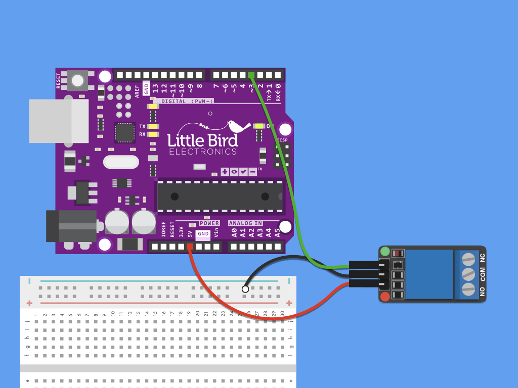
Connect IN on relay to Pin 3 on Arduino
Step 7 — Insert batteries into battery holder
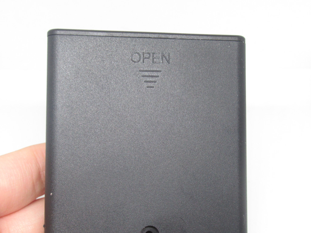
The battery holder enclosure contained in the kit will fit 4 x AA batteries. Insert 4 X AA batteries into the case. Make sure that the '+' side of a battery cell is connected to the '+' side of the battery enclosure, and '-' of a battery cell to '-' of enclosure.
There is a switch on the battery enclosure, to turn it 'ON' and 'OFF'
Step 8 — Connect black wire (battery holder) to negative power rail
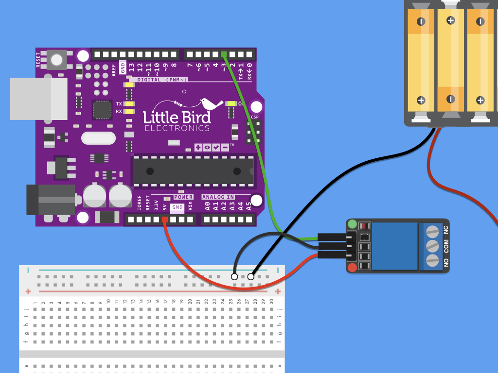
Connect the '-' black wire from battery pack to the negative power rail on the breadboard
Step 9 — Connect black wire of pump to negative power rail
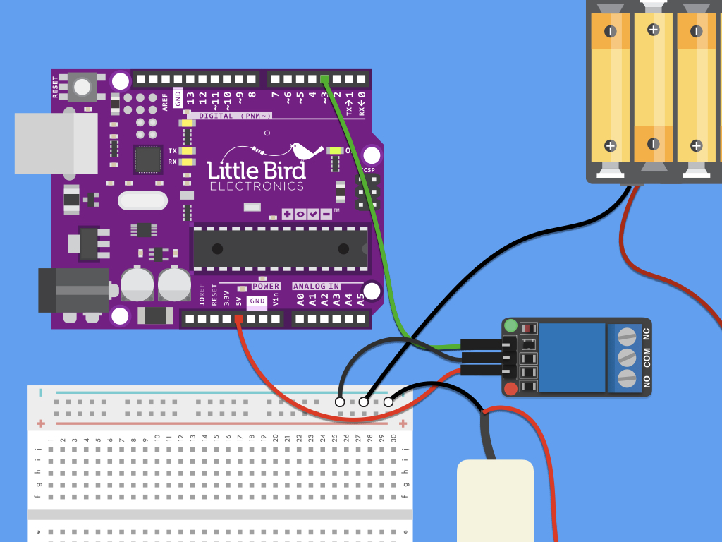
Next, connect the black wire of pump to negative power rail
Step 10 — Connect soil moisture sensor to module
Connect two F-F jumper wires from the soil moisture sensor probe to the comparison module included in the kit.
Step 11 — Connect AO to A0
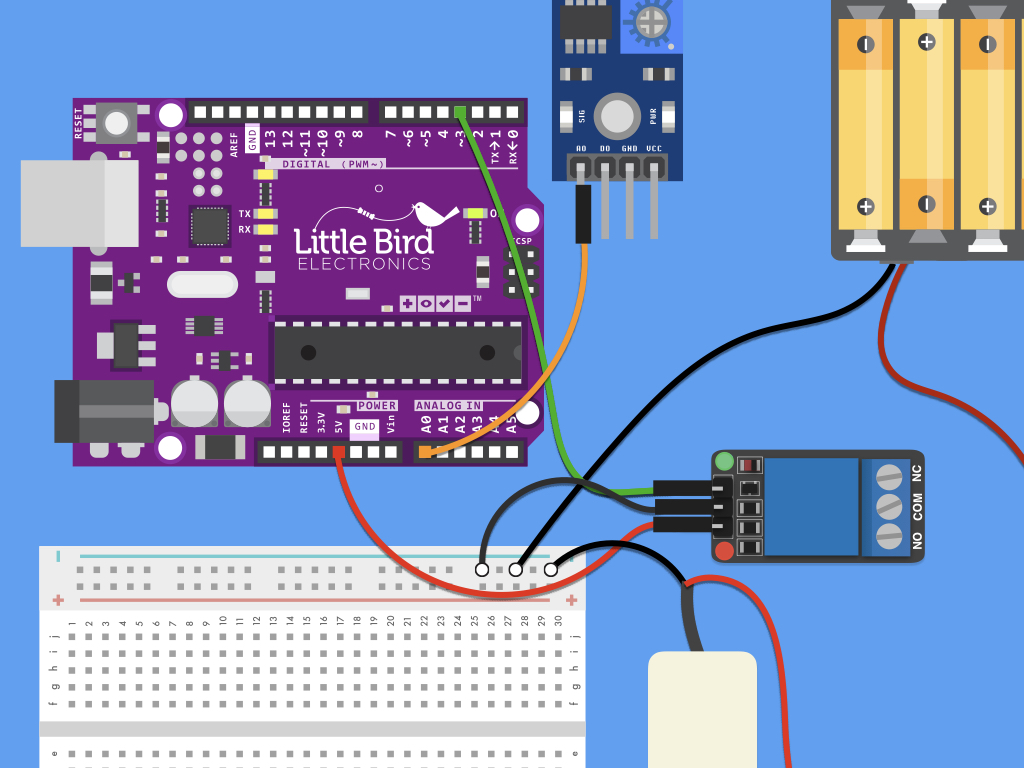
Connect a F-M jumper wire from AO on the module to A0 on Arduino
Step 12 — Connect GND (on module) to GND

Connect a F-M jumper wire from GND on the module to GND on Arduino
Step 13 — Connect VCC (on module) to 3.3V
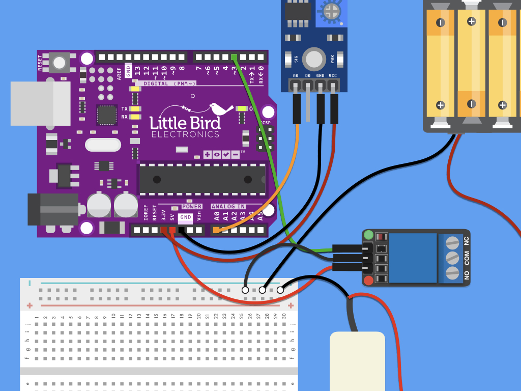
Connect a F-M jumper wire from VCC on the module to 3.3V on the Arduino
Step 14 — Connect red wire of pump to NC

Connect red wire of pump to NC.
You may need to use a small jewelers phillips screwdriver to loosen the holding before plugging in the wire, and then tightening it again.
Step 15 — Connect red wire (battery holder) to COM

Connect the '+' red wire from battery holder to COM on the relay.
You may need to use a small jewelers phillips screwdriver to loosen the holding before plugging in the wire, and then tightening it again.
Step 16 — Connect negative power rail to GND

Connect a M-M wire from the negative power rail of breadboard, to GND pin on Arduino
Next, we will get started with programming the Arduino, so connect it to a computer with the Arduino IDE installed.
Step 17 — The code
int motorPin = 3; // pin that turns on the motor
int blinkPin = 13; // pin that turns on the LED
int watertime = 5; // how long it will be watering (in seconds)
int waittime = 1; // how long to wait between watering (in minutes)

void setup()
{
  pinMode(motorPin, OUTPUT); // set Pin 3 to an output
  pinMode(blinkPin, OUTPUT); // set pin 13 to an output
  Serial.begin(9600);
}

void loop()
{
  int moisturePin = analogRead(A0); //read analog value of moisture sensor
  int moisture = ( 100 - ( (moisturePin / 1023.00) * 100 ) ); //convert analog value to percentage
  Serial.println(moisture);
  if (moisture < 40) { //change the moisture threshold level based on your calibration values
    digitalWrite(motorPin, HIGH); // turn on the motor
    digitalWrite(blinkPin, HIGH); // turn on the LED
    delay(watertime * 1000);      // multiply by 1000 to translate seconds to milliseconds
  }
  else {
    digitalWrite(motorPin, LOW);  // turn off the motor
    digitalWrite(blinkPin, LOW);  // turn off the LED
    delay(waittime * 60000);      // multiply by 60000 to translate minutes to milliseconds
  }

}
Upload this code to the Arduino!
To adjust how long it will be watering each time, simply change :
int watertime = 5;
int watertime = 5;
To adjust the wait time between watering, simply change:
int waittime = 1;
To adjust the moisture threshold level, change the conditional statement:
if (moisture < 40)
Save this sketch. Then go to the next step to calibrate your soil moisture sensor. This is an important next step that we recommend as different soil types will yield different measurements.
Step 18 — Code to calibrate soil moisture sensor
void setup() {
  Serial.begin(9600); // initialize serial communication
}

void loop() {
  int moistureVal = analogRead(A0);  // read the input on analog pin 0:
  Serial.println(moistureVal); // print out the analog val
  delay(30);
}
Now that you have connected the kit with an Arduino, the 'moisture' threshold value found in the sketch above may need to be modified based on what values your sensor outputs when the sensor is completely dry, compared to when the sensor is completely submerged in water.
Copy this code and upload it to your Arduino to get analog readings for calibration
Copy this code and upload it to your Arduino to get analog readings for calibration
Conduct a test using a bowl of water. Make note of the analog value when the probes are not in water. Submerge it in a shallow glass of water, and watch the analog value drop
Conduct another test, this time using soil. Get measurements when the soil is completely dry.
Do the same when the soil has been watered, but be careful not to over-water it.
View the readings in the Serial Monitor in the Arduino IDE by clicking on Tools > Serial Monitor
The more water content in the soil, the lower the analog measurements will be.
Step 19 — Stand-alone circuit
Follow these steps to connect the automatic plant watering kit without an Arduino. First, connect 2x F-F jumper wires from the soil moisture sensor probe to its comparison module.
Next, connect DO pin on the comparison module to IN pin on relay.
Connect VCC pin on comparison module to breadboard's positive power rail. Use a M-F jumper wire.
Connect GND pin on comparison module to breadboard's negative power rail. Use another M-F jumper wire.
For the battery enclosure, connect its black wire to breadboard's negative power rail
Connect red wire of battery enclosure to breadboard's positive power rai
For the relay, connect VCC pin to breadboard's positive power rail
Connect GND pin on relay to breadboard's negative power rai
Connect the relay's COM pin to positive power rail on the breadboard.
You may need to use a screwdriver to loosen the holding before plugging in the wire, and then tightening it again.
The mini water pump has two wires, connect its red wire to NC on relay
Likewise, you may need to use a screwdriver to insert the wire
Connect the mini water pump's black wire to negative power rail on breadboard.
Step 20 — Soil moisture calibration (standalone)
Finally, to get useful measurements from the soil moisture sensor, it's time to calibrate it. We recommend calibrating it as different types of soil can affect the sensor readings differently.
If you have connected the kit as a stand-alone without an Arduino, you can calibrate the soil moisture sensor by turning the potentiometer found on the comparison module. Use a small jewelers phillips screwdriver.
- Turn it clockwise to increase sensitivity,
- Turn it counterclockwise to decrease the sensitivity.
Step 21 — Complete build
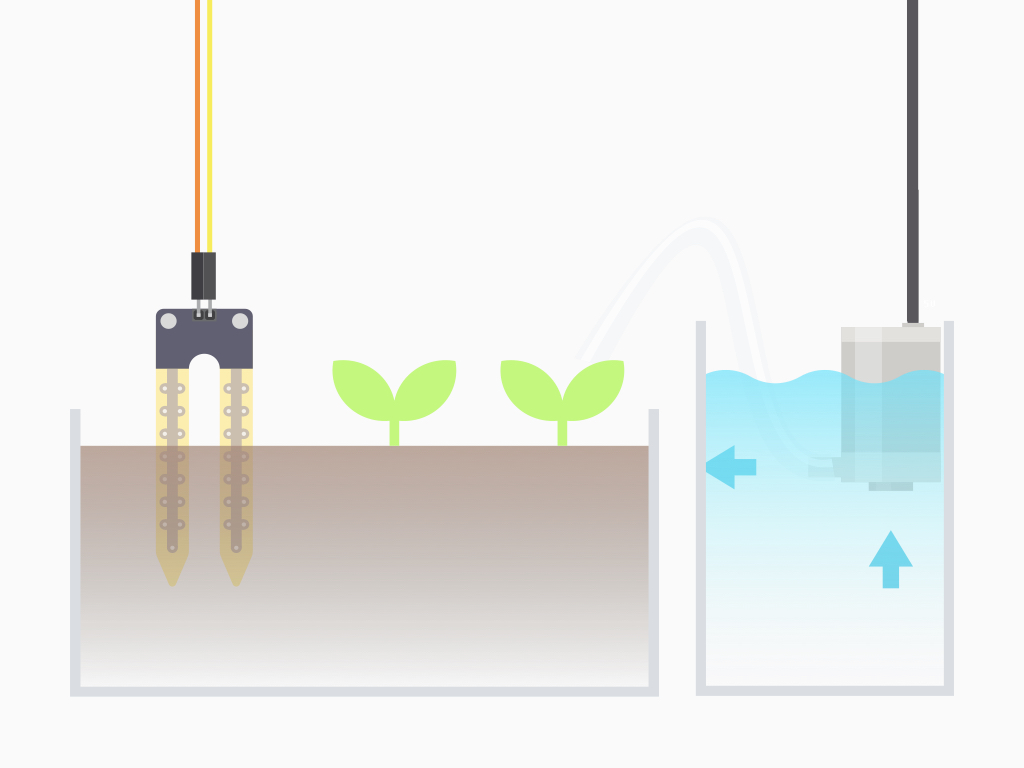
Connect the tube to the submersible water pump as shown in the diagram.
Place the pump in a container of water.
Insert the soil moisture sensor probe into your potted plant.
Power up the circuit. After which, when the soil moisture level goes below the set threshold moisture level, it will be automatically watered.
You may want to go one step further: move the circuit from the breadboard to a more permanent set-up by using a perma-protoboard or perfboard.
Parts List
Required Parts (1)
Optional Extras (1)
Project Summary
2 parts total
Required parts
$11.75
Optional extras
+$19.55
Total (required)
$11.75
Unavailable items will be skipped
