
Beginner
Using LEDs with micro:bit
Learn to use multiple LEDs with the micro:bit and make a light show
By Cherie Tan
A light-emitting diode (LED) is a semiconductor device that emits light when an electric current passes through it.
In this guide, you will learn to connect external LEDs to the micro:bit, and create a light show.
Complete this guide to learn how to use external LEDs with the micro:bit!
Before we begin, let's take a look at the external LED.
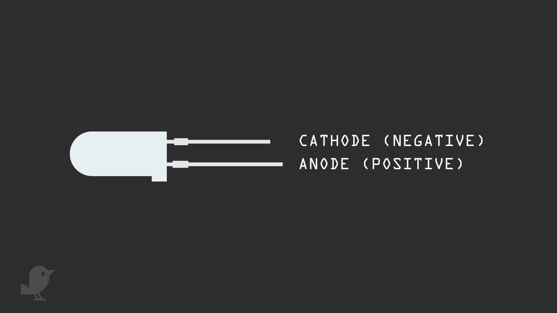
The LED has two leads, a negative lead and a positive lead.
The longer leg is the positive lead, also called the anode.
The shorter leg is the negative lead, also called the cathode. This will be connected to GND.
The LED has two leads, a negative lead and a positive lead.
The longer leg is the positive lead, also called the anode.
The shorter leg is the negative lead, also called the cathode. This will be connected to GND.
If the legs are trimmed, you can also tell by looking at the flat edge on the LED's outer casing. The pin closest to the flat edge will be the negative pin, the cathode pin.
Step 1 — LED
Before we begin, let's take a look at the external LED.
The LED has two leads, a negative lead and a positive lead.
The longer leg is the positive lead, also called the anode.
The shorter leg is the negative lead, also called the cathode. This will be connected to GND.
The LED has two leads, a negative lead and a positive lead.
The longer leg is the positive lead, also called the anode.
The shorter leg is the negative lead, also called the cathode. This will be connected to GND.
If the legs are trimmed, you can also tell by looking at the flat edge on the LED's outer casing. The pin closest to the flat edge will be the negative pin, the cathode pin.
Step 2 — Connect Cathode to GND
Step 3 — Add a resistor
Step 4 — Connect Anode to P2
Step 5 — MakeCode
basic.forever(function () {
    pins.digitalWritePin(DigitalPin.P2, 0)
    basic.pause(500)
    pins.digitalWritePin(DigitalPin.P2, 1)
    basic.pause(500)
})
Copy and paste this code to the Javascript interface.
Programming the external LED is similar to how it was done for the Two Colour LED module. We've used 'pins.digitalWritePin()' to turn the LED on and off.
Step 6 — MakeCode for Light Show
led.enable(false)
basic.forever(function () {
    pins.digitalWritePin(DigitalPin.P0, 1)
    basic.pause(1000)
    pins.digitalWritePin(DigitalPin.P1, 1)
    basic.pause(1000)
    pins.digitalWritePin(DigitalPin.P2, 1)
    basic.pause(1000)
    pins.digitalWritePin(DigitalPin.P3, 1)
    basic.pause(1000)
    pins.digitalWritePin(DigitalPin.P4, 1)
    basic.pause(1000)
    pins.digitalWritePin(DigitalPin.P4, 0)
    basic.pause(1000)
    pins.digitalWritePin(DigitalPin.P3, 0)
    basic.pause(1000)
    pins.digitalWritePin(DigitalPin.P2, 0)
    basic.pause(1000)
    pins.digitalWritePin(DigitalPin.P1, 0)
    basic.pause(1000)
    pins.digitalWritePin(DigitalPin.P0, 0)
    basic.pause(1000)
})
Copy and paste this code into the Javascript interface.
Upload it to the micro:bit and you should see the LEDs lighting up one after another and then going off. Pins 3 and 4 GPIO are shared with the micro:bit's LED screen. To use Pins 3 and 4 for the light show, we will first disable the LED screen by using the 'led enable false' block on start
Step 7 — Arduino Code for Light Show
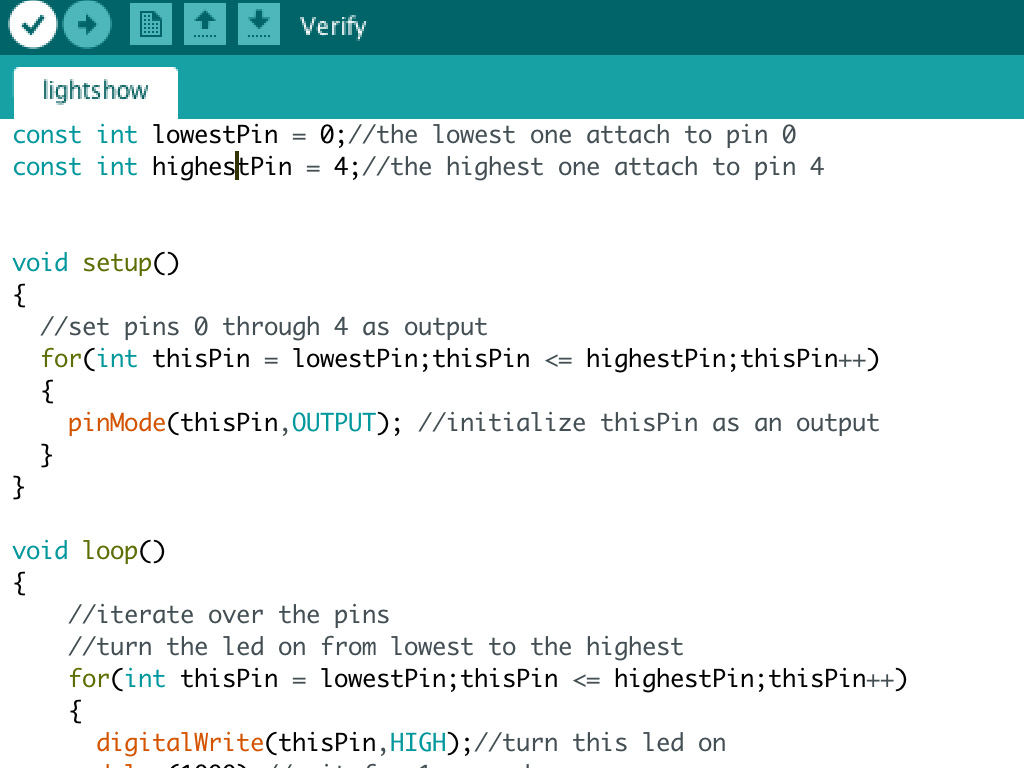
const int lowestPin = 0;//the lowest one attach to pin 0
const int highestPin = 4;//the highest one attach to pin 4


void setup()
{
  //set pins 0 through 4 as output
  for(int thisPin = lowestPin;thisPin <= highestPin;thisPin++)
  {
    pinMode(thisPin,OUTPUT); //initialize thisPin as an output
  }
}

void loop()
{
    //iterate over the pins
    //turn the led on from lowest to the highest
    for(int thisPin = lowestPin;thisPin <= highestPin;thisPin++)
    {
      digitalWrite(thisPin,HIGH);//turn this led on
      delay(1000);//wait for 1 second
    }
    //fade from the highest to the lowest
    for(int thisPin = highestPin;thisPin>=lowestPin;thisPin--)
    {
      digitalWrite(thisPin,LOW);//turn this led off
      delay(1000);//wait for 1 second
    }
  }
Optionally, you may want to use the micro:bit with the Arduino IDE. Open the Arduino IDE. If you have not got it installed, please follow our previous guide on how to install and set up the Arduino IDE for micro:bit. It requires a few more steps than just installing the IDE, to get it working with the micro:bit, so please follow that guide.
Then, copy and paste this code to the Arduino IDE
Step 8 — Upload the code
It's time to upload the code to the micro:bit. In the Arduino IDE, click on the tick icon on the top left-hand corner to verify the code.
Then click on the upload button next to it.
Wait for the code to finish uploading. You will know it is done when it states 'Done uploading' on the bottom left-hand corner.
Step 9 — Using multiple light-emitting diodes
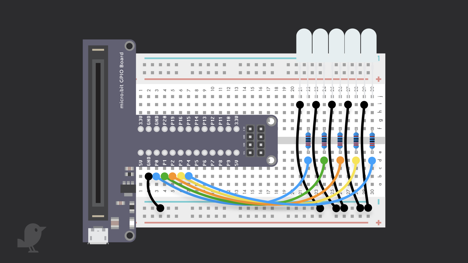
To use more than one external LED, follow these steps. We'll use multiple LEDs with the micro:bit to create a light show. So go on and add a four more LEDs as shown in the diagram.
We'll use a total of five LEDs to create a light show by programming the micro:bit using the MakeCode editor, and then with the Arduino IDE.
Each of the cathode (negatively charged lead) of the LEDs needs to be connected to the negative rail.
Each of the anode (positively charged lead) of the LEDs need to be connected to P0 to P4, with the use of a resistor.
Remember to connect the negative rail to a GND pin.
Parts List
Required Parts (1)
Project Summary
1 part total
Required parts
$79.35
Total (required)
$79.35
Unavailable items will be skipped
