Measure Temperature and Humidity with micro:bit
Learn to use an external temperature sensor with micro:bit
Written By: Cherie Tan
Difficulty
Medium
Steps
15
While the micro:bit can estimate the ambient temperature, it isn't as accurate as using an external temperature sensor. This is because the micro:bit actually measures the temperature of a silicon die on its CPU.
In this guide, you will learn to use an external temperature sensor module and the micro:bit to make a temperature and humidity display!
After completing this guide, you can use it to detect the temperature around you much more accurately.
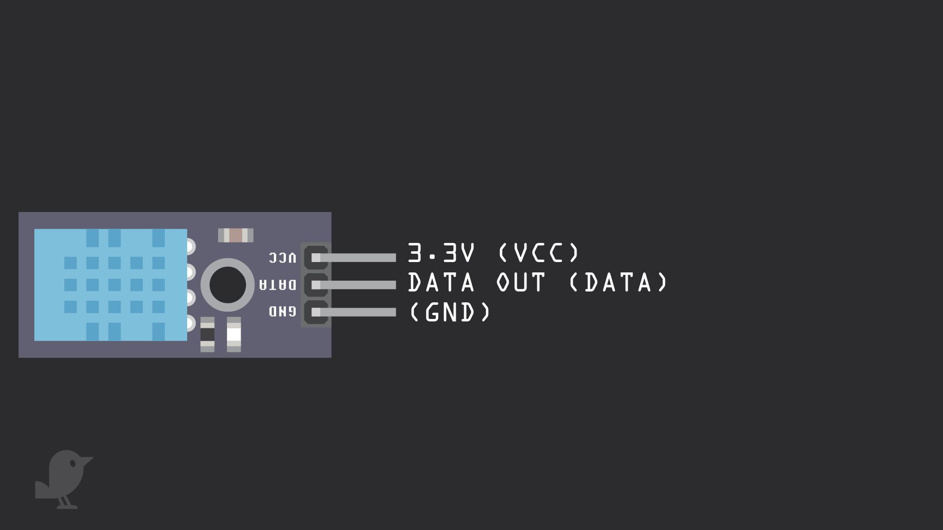
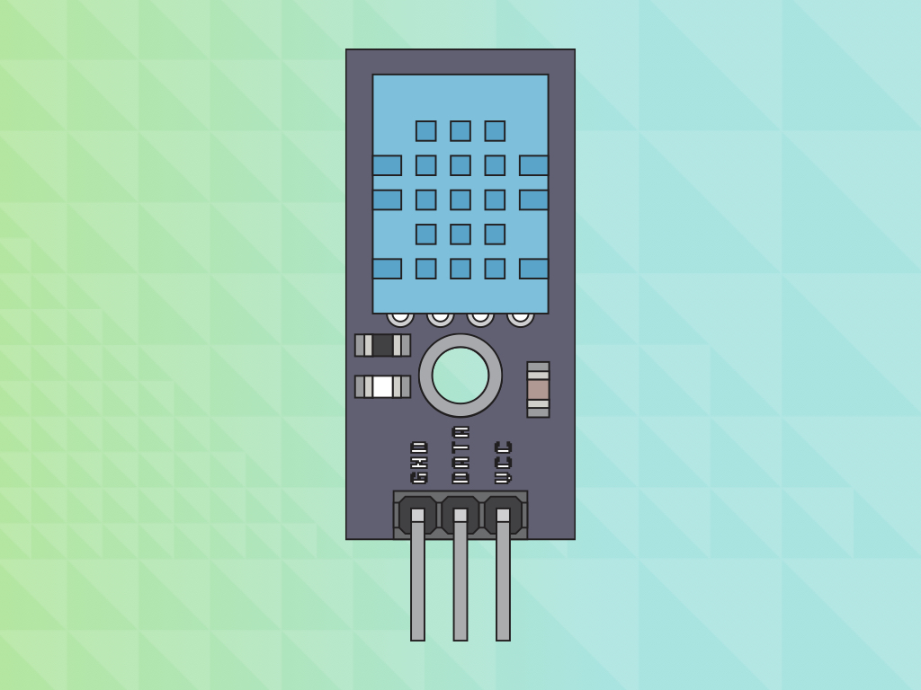
Let's take a closer look at the DHT11 Module that we'll be working with today. It is capable of both temperature and humidity sensing. It has three pins:
GND: In electronics, we define a point in a circuit to be a kind of zero volts or 0V reference point, on which to base all other voltage measurements. This point is called ground or GND.
DATA: The DHT11 measures the air and outputs a digital signal on this pin.
3.3V : 'VCC' stands for Voltage Common Collector, we'll connect the VCC pin to 3.3V on the micro:bit
Voltage is the difference in electric potential between two points. As it is difficult to talk about voltage without a reference point, we need another point to compare it to.
It can be programmed in MakeCode editor and the Arduino IDE. Skip to step 7 to program it with the Arduino IDE.
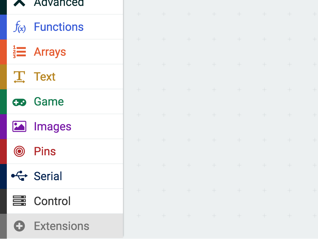
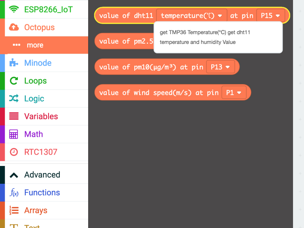
Now that we've got the DHT11 hooked up to the micro:bit, let's program it in the MakeCode editor. Programming the DHT11 in MakeCode is simple with the proper extension. It's got all the blocks required which will allow you to easily interface with the DHT11. To get the extension, first, click on the 'Extensions' tab
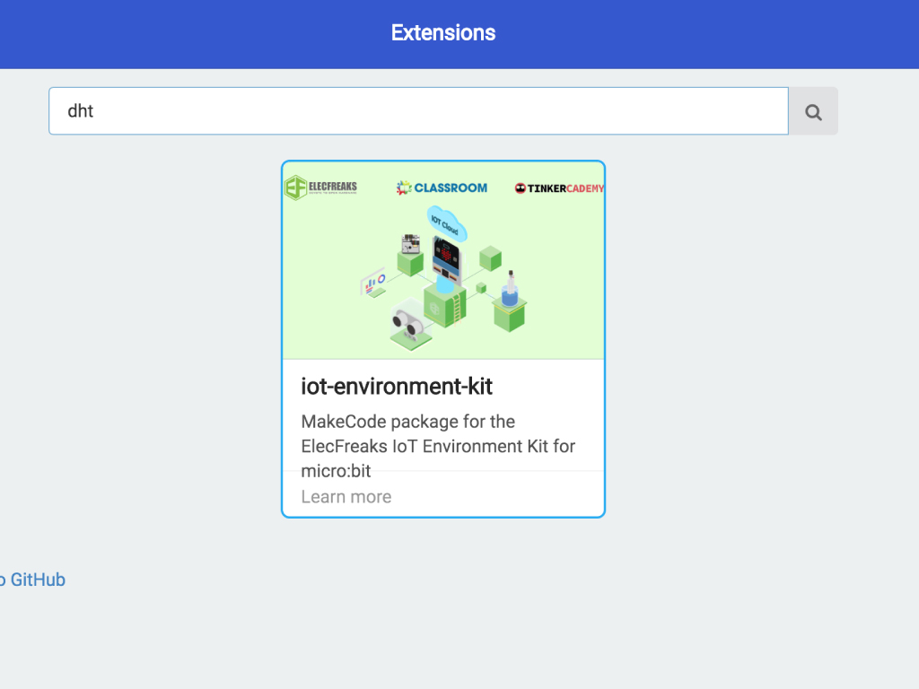
Type 'dht' in the search field
Click on 'iot-environment-kit'
The extension will then be automatically added to the editor
basic.forever(function () {
    basic.showString("Temp:")
    basic.showNumber(Environment.temperature(Environment.DHT11Type.DHT11_temperature_C, DigitalPin.P0))
    basic.showString("Hum:")
    basic.showNumber(Environment.temperature(Environment.DHT11Type.DHT11_humidity, DigitalPin.P0))
})
Add this code to the Javascript interface in the MakeCode editor.
Upload this code to your micro:bit and watch the temperature and humidity values scroll along the LED display.
We've set it as pin P0 as the DATA pin on the DHT11 is connected to P0 on the micro:bit. This MakeCode will also work if you have the DATA pin connected to either Pin 1,2,5,8, or 15.
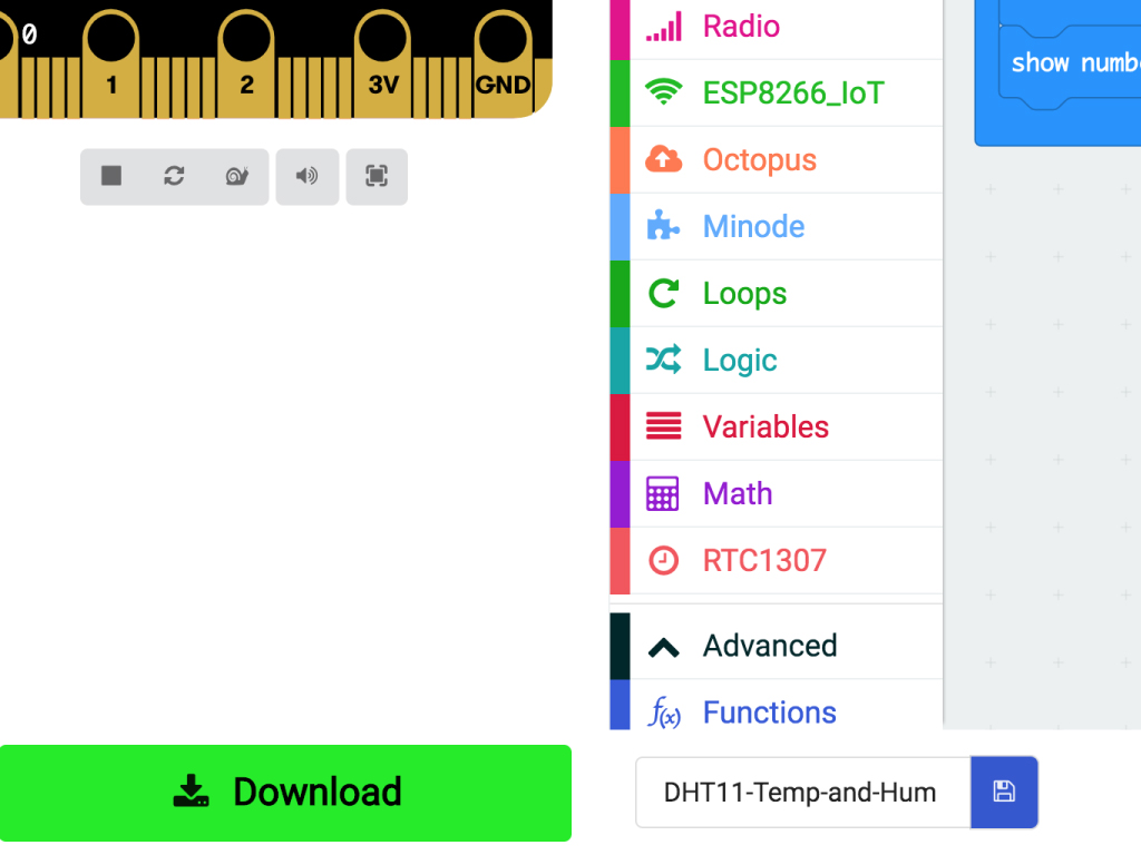
To upload the code to the micro:bit, first, connect the micro:bit to the computer via microUSB cable
Click on the 'Download' button and the hex file will be automatically downloaded to your 'Downloads' folder
Drag and drop the downloaded .hex file to the MICROBIT drive
Leave the micro:bit alone for a few seconds as it blinks. The code is uploading!
Alternatively, you can also program the micro:bit to work with the DHT11 in the Arduino IDE. Why would you want to do this? Programming it in the Arduino IDE may give you more flexibility. For instance, you could use another display rather than the micro:bit's LED display. To use it with the Arduino IDE, first, you will need to download the required package. Open the Arduino IDE. If you have not got it installed, please follow our previous guide on how to install and set up the Arduino IDE for micro:bit.
Click on File > New
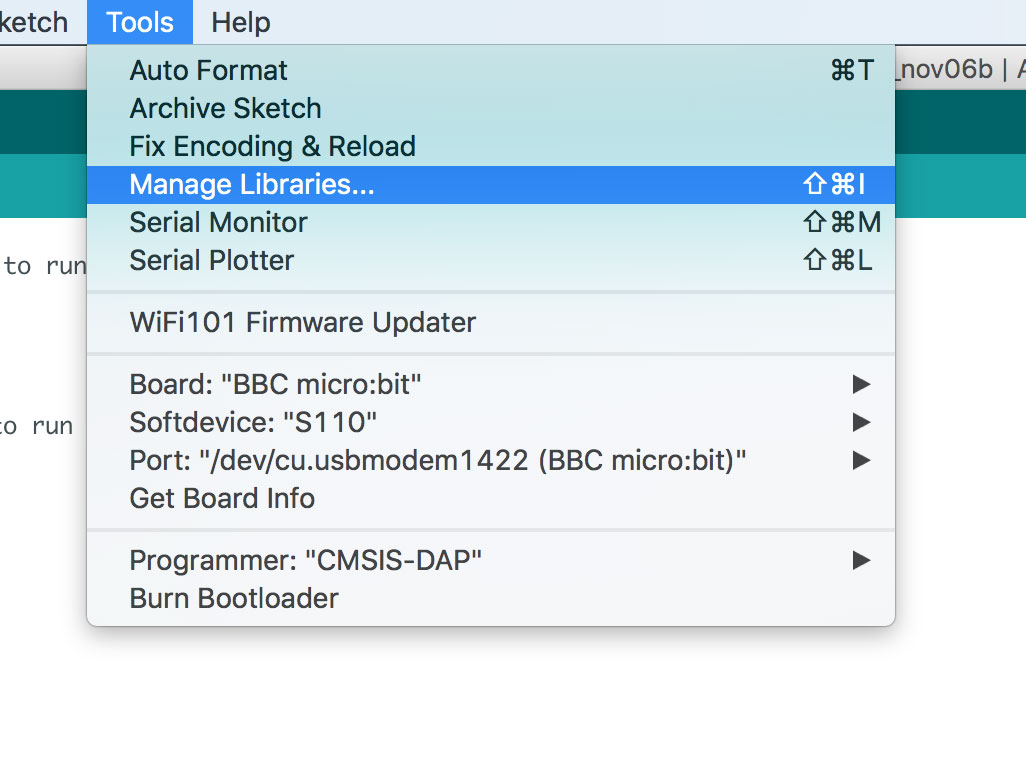
Click on 'Tools'
Click on 'Manage libraries'
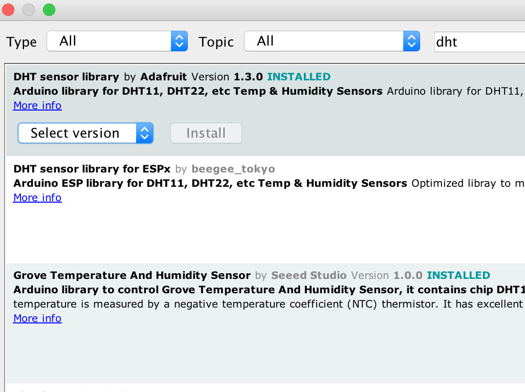
Type 'DHT' in the search bar
Click on the install button for 'DHT sensor library'
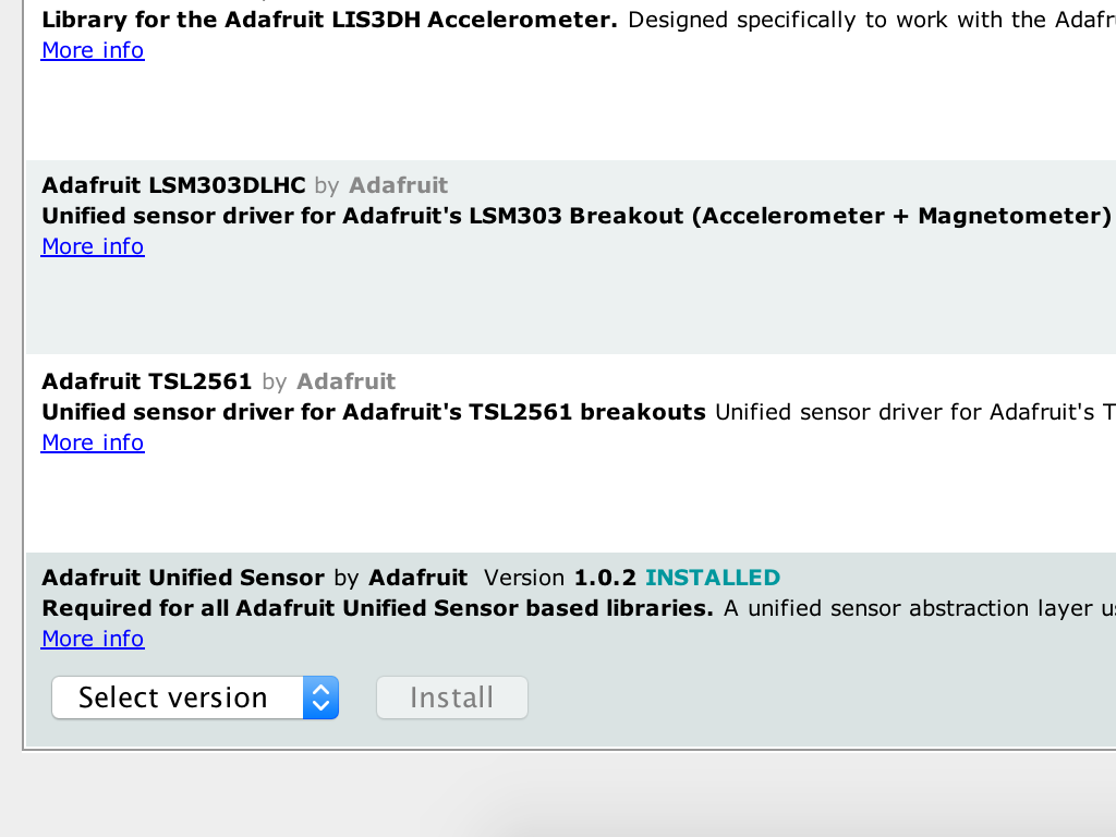
An additional library may be required. If you get an error when trying to upload the code, please also search for and download 'Adafruit Unified Sensor' in the library manager.
#include "DHT.h"
#define DHTPIN 0     // what digital pin we're connected to
#define DHTTYPE DHT11   // DHT 11

DHT dht(DHTPIN, DHTTYPE);
Copy the following code into the Arduino IDE.
There's an important library required here to get a temperature reading from the DHT11 using the micro:bit. It is included with the command: #include "DHT.h"
Next, we need to indicate which pin is connected to the sensor's DATA pin. We connected it to Pin 0, : #define DHTPIN 0
The next definition involves indicating which DHT sensor type is being used. The sensor we are using today is the DHT11, however there are other models such as the DHT22.
This is done by using: #define DHTTYPE DHT11
void setup() {
  Serial.begin(9600);
  Serial.println("DHT11 Sensor");

  dht.begin();
}
Next, add the following code in the void setup() which is empty at the moment.
The Serial.begin() command sets the data rate for communicating with the computer. We will use 9600 bits per second (baud).
Next, to initialize the device, we use the command dht.begin();
Then, we will print the string, "DHT11 Sensor" in the serial monitor for viewing.
void loop() {
  // Wait a few seconds between measurements.
  delay(2000);

  // Read Humidity
  float h = dht.readHumidity();
  // Read temperature as Celsius (the default)
  float t = dht.readTemperature();

  // Check if any reads failed and exit early (to try again).
  if (isnan(h) || isnan(t)) {
    Serial.println("Failed to read from DHT sensor!");
    return;
  }

  Serial.println("Humidity: ");
  Serial.print(h);
  Serial.print(" %\t");
  Serial.print("\n");
  Serial.println("Temperature: ");
  Serial.print(t);
  Serial.print("\n");

}
Now, in void loop() add the following code.
- delay(2000); ensures that there are two seconds between each measurement.
- We then create two float variables, h and t.
h will store the humidity and t will store the temperature. How are they stored? Using the dht library, we can simply use the commands: dht.readHumidity(); and dht.readTemperature(); and store them in each variable respectively.
To check if the sensor has failed to get a reading, we use an if statement"
if(isnan(h) || isnan(t))
This means "if h is not true or t is not true" then print to the serial monitor "Failed to read from DHT sensor!".
This means "if h is not true or t is not true" then print to the serial monitor "Failed to read from DHT sensor!".
Finally, we want to print the temperature and humidity readings to Arduino IDE's in-built serial monitor display. It's a simple display window that we can output values to.
We simply use the command: Serial.print(t) and Serial.print(h)
\t prints a tab. \n will create a new line so it will look more readable on the monitor!
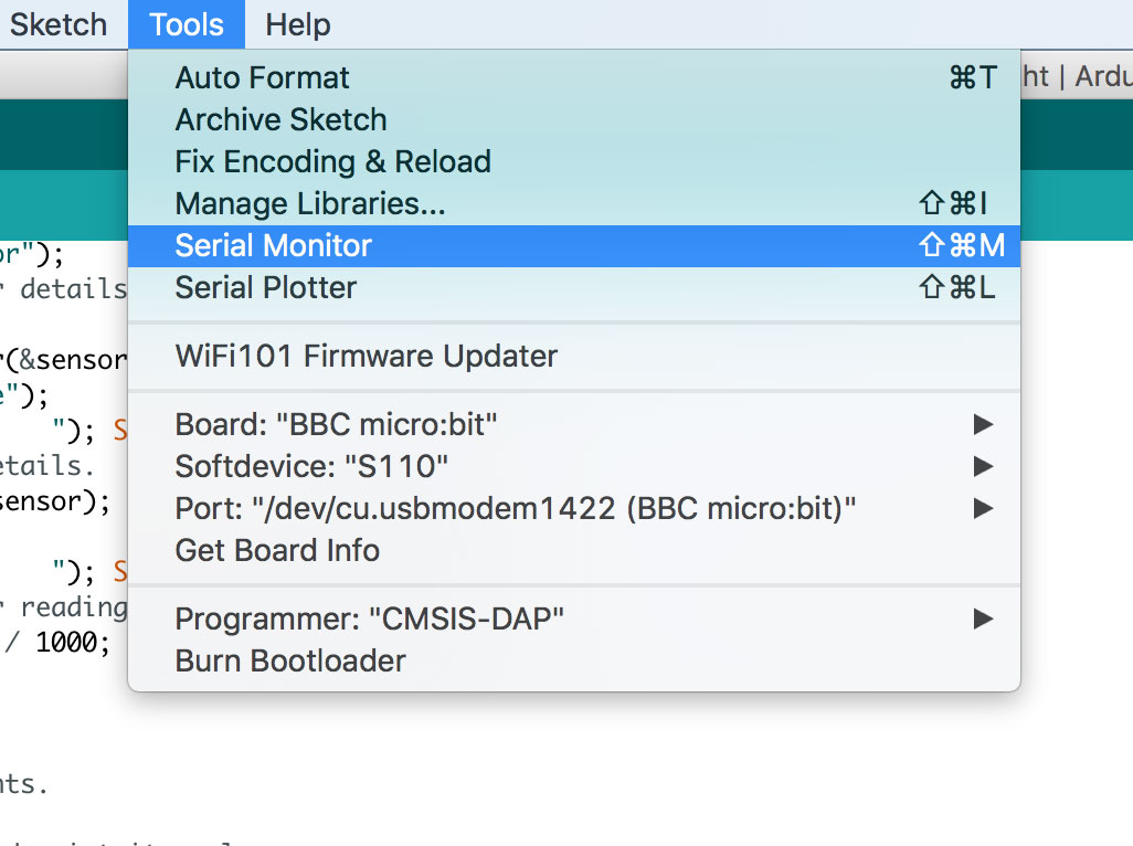
Finally, let's open up the serial monitor. Click on Tools > Serial Monitor
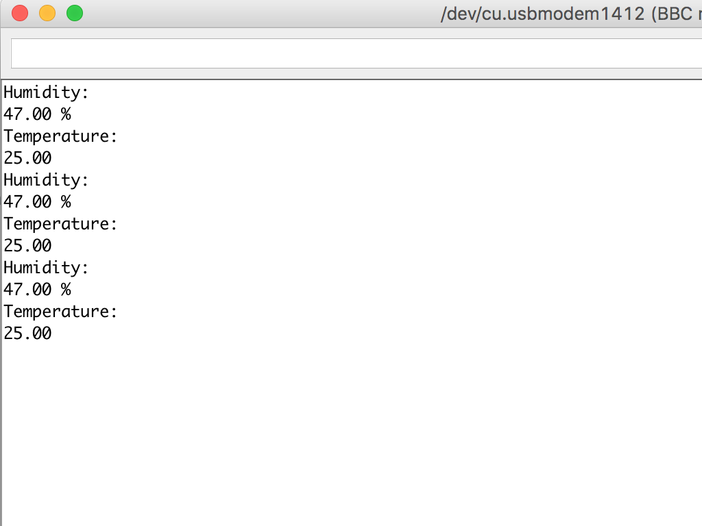
You should now see temperature and humidity readings taken every two seconds.
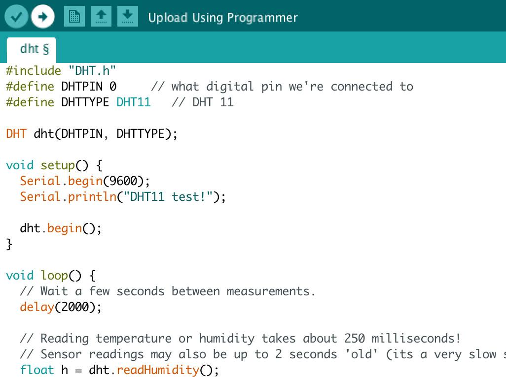
#include "DHT.h"
#define DHTPIN 0     // what digital pin we're connected to
#define DHTTYPE DHT11   // DHT 11

DHT dht(DHTPIN, DHTTYPE);

void setup() {
  Serial.begin(9600);
  Serial.println("DHT11 test!");

  dht.begin();
}

void loop() {
  // Wait a few seconds between measurements.
  delay(2000);

  // Read Humidity
  float h = dht.readHumidity();
  // Read temperature as Celsius (the default)
  float t = dht.readTemperature();

  // Check if any reads failed and exit early (to try again).
  if (isnan(h) || isnan(t)) {
    Serial.println("Failed to read from DHT sensor!");
    return;
  }

  Serial.println("Humidity: ");
  Serial.print(h);
  Serial.print(" %\t");
  Serial.print("\n");
  Serial.println("Temperature: ");
  Serial.print(t);
  Serial.print("\n");

}
Copy this code and upload it to your Micro:bit using the Arduino IDE.
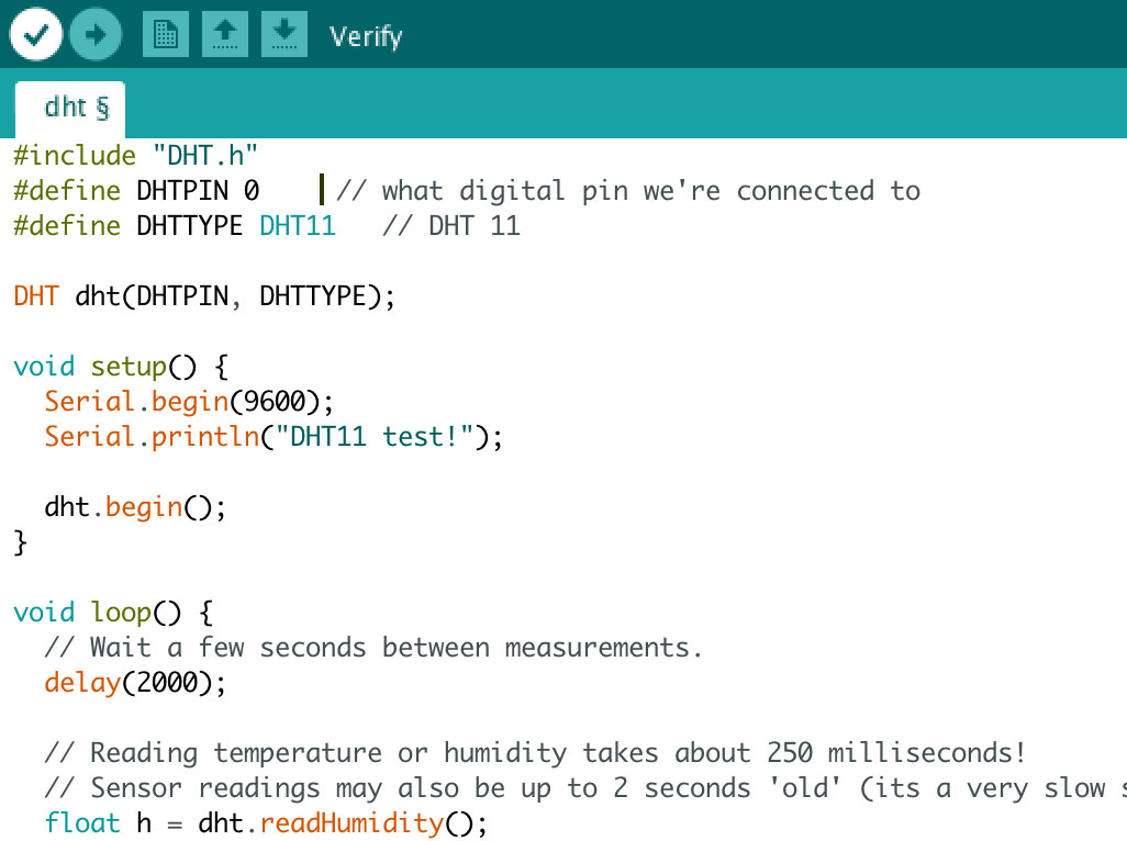
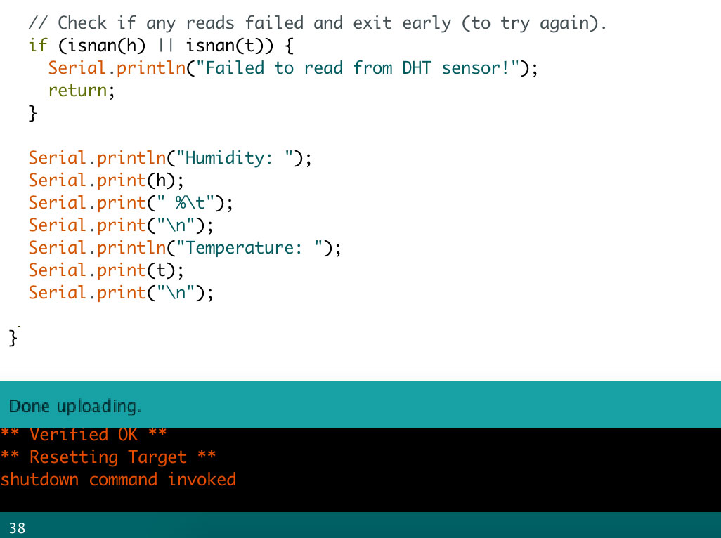
That's it! It's time to upload the code to the micro:bit. Click on the tick icon on the top left-hand corner to verify the code.
Then click on the upload button next to it.
Wait for the code to finish uploading. You will know it is done when it states 'Done uploading' on the bottom left-hand corner.