SD Card Module with Arduino
Record sensor measurements to an SD card module
Written By: Cherie Tan
Difficulty
Medium
Steps
22
An SD (Secure Digital) card is ideal for both data storage as well as for data transfer. However, by itself, an Arduino board is not able to use SD cards. With an SD card module, this is made possible.
In this guide, learn to hook up an SD card module to a Arduino Pro Mini 328 - 3.3V/8 MHz, and a DHT11 temperature and humidity sensor. Learn to gather humidity readings from the DHT11 sensor which will be recorded to a text file.
Complete this guide to start data-logging with an SD card module and an Arduino.
While you could use the EEPROM on the Arduino to store data, it has a much smaller capacity than SD cards, as well as a limited endurance.
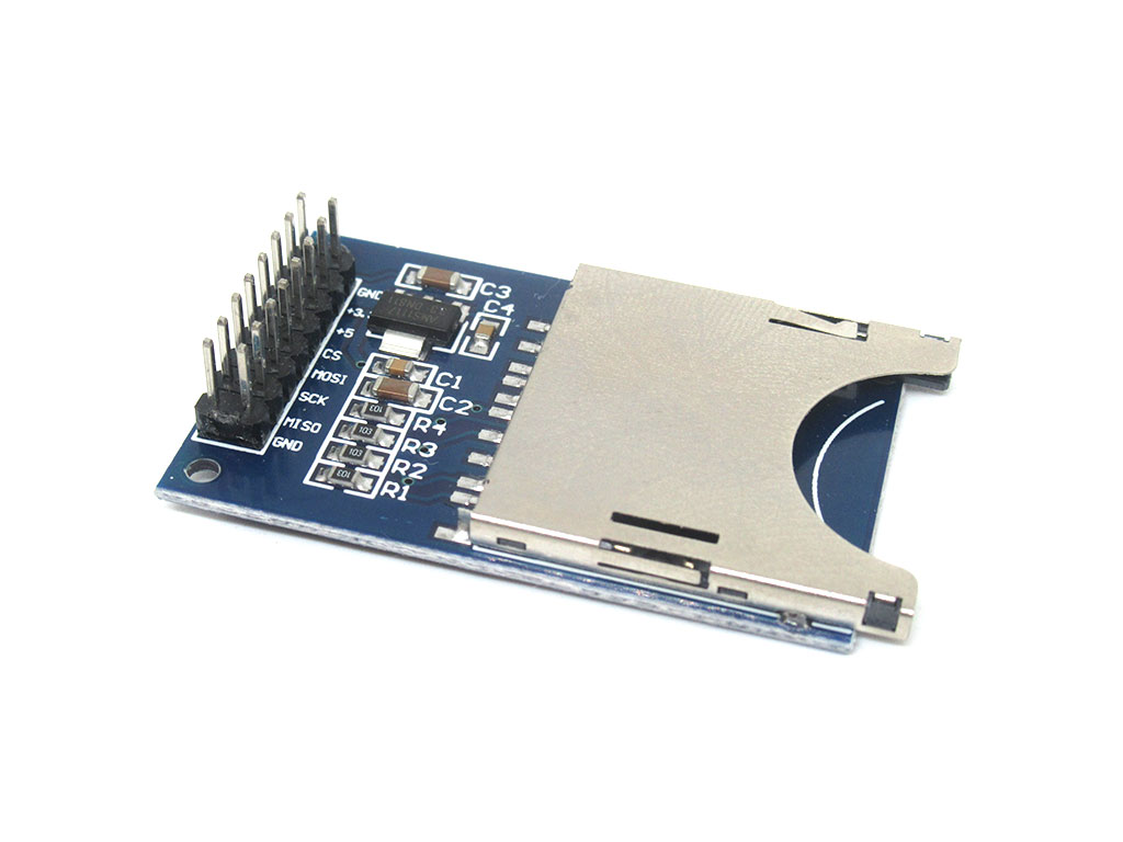
An SD (Secure Digital) card is ideal for both data storage as well as for data transfer; you could directly transfer photos without a USB cable from a camera to computer, simply by taking out the SD card, and connecting it to the computer. You could also use it with an Arduino. However, by itself, an Arduino board is not able to use SD cards.
This SD card module enables you to do so. It is ideal for low-power, data-logging or media-related applications, in need of high accessibility and a huge capacity for data storage.
In this guide, an SD card module will be used with an Arduino Pro Mini - 3.3V and a DHT11 temperature and humidity sensor. The temperature data will be recorded in a text file onto an SD card.
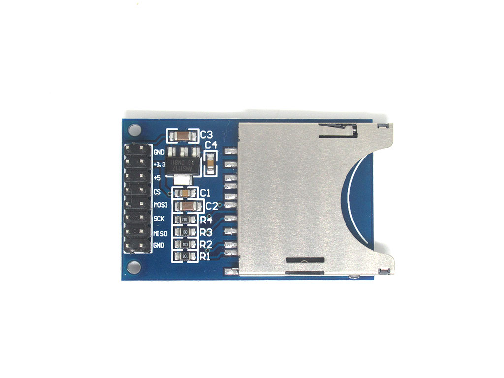
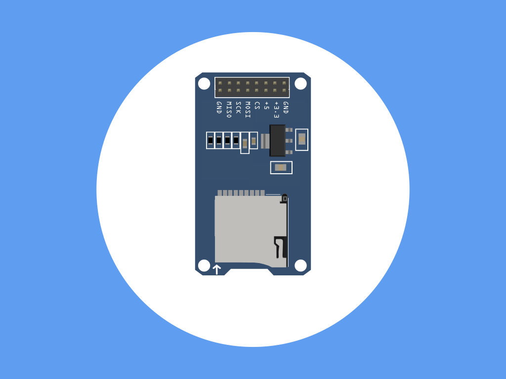
Take a look at the SD card module and you'll notice that there are eight pins:
GND: Ground
+3.3V: Power pin. Attach to 3.3V on the Arduino
+5: Another power pin, we recommend using a voltage level converter when connecting to a 5V Arduino.
CS: Chip Select
MOSI: Master Out Slave In
SCK: Clock signal
MISO: Master In Slave Out
GND: Another ground pin
GND: Ground
+3.3V: Power pin. Attach to 3.3V on the Arduino
+5: Another power pin, we recommend using a voltage level converter when connecting to a 5V Arduino.
CS: Chip Select
MOSI: Master Out Slave In
SCK: Clock signal
MISO: Master In Slave Out
GND: Another ground pin
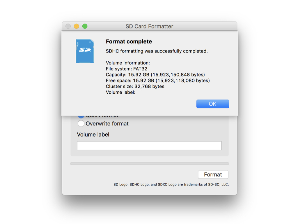
Connect an SD card to your computer, and open up an SD Card Formatter software such as SD Formatter 4.0 for Windows or Mac. If you haven't yet got one, run it and install the software.
Insert the SD card into your SD card reader, then look at the drive letter that shows up in the left hand column of Windows Explorer, or Finder on the Mac.
In SD Formatter, select the correct drive letter for the SD card, then click on 'Format'.
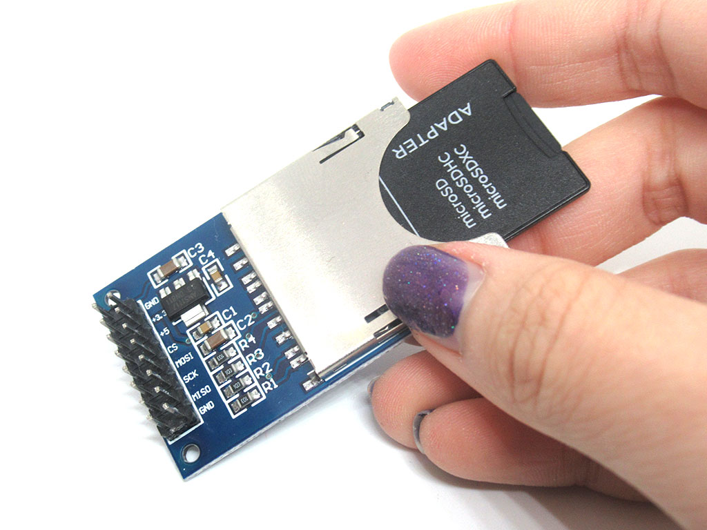
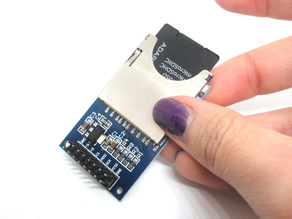
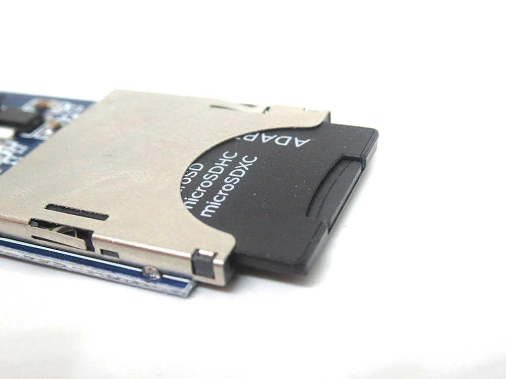
Insert an SD card into the SD card slot.
Push it into the slot and you should hear a 'click' sound.
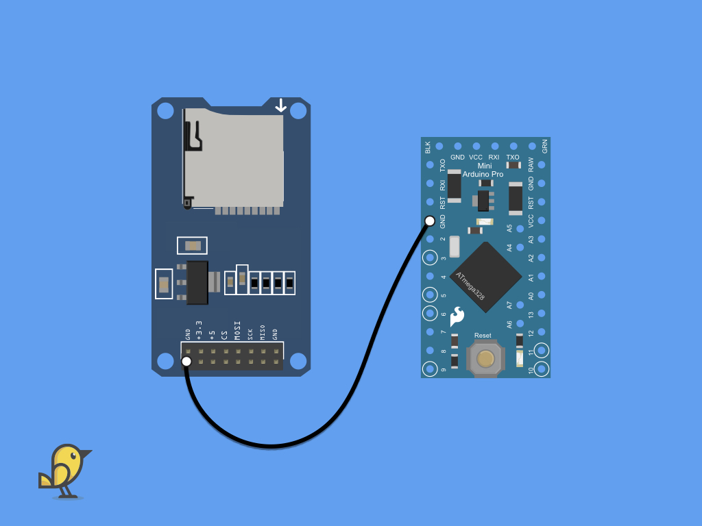
Attach a F-F black jumper wire from GND on the SD card module to GND on the Pro Mini.
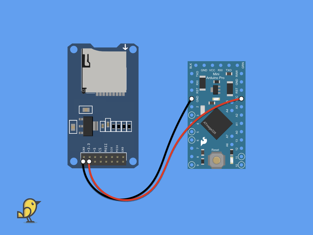
Attach a F-F red jumper wire from 3.3V on the SD card module to VCC on the Pro Mini.
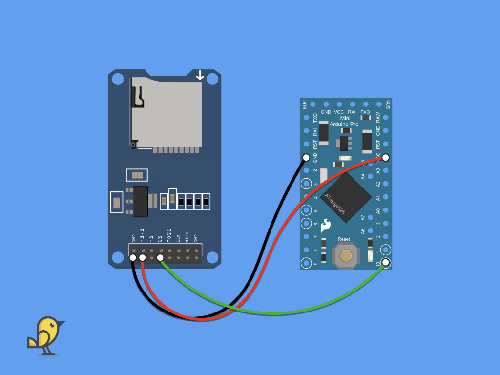
Attach a F-F black jumper wire from CS on the SD card module to digital pin 10 on the Pro Mini.
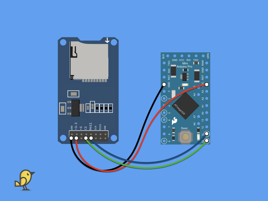
Attach a F-F jumper wire from MOSI on the SD card module to digital pin 11 on the Pro Mini.
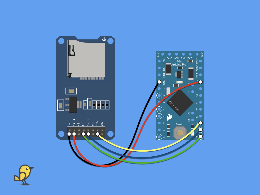
Attach a F-F jumper wire from MISO on the SD card module to digital pin 12 on the Pro Mini.
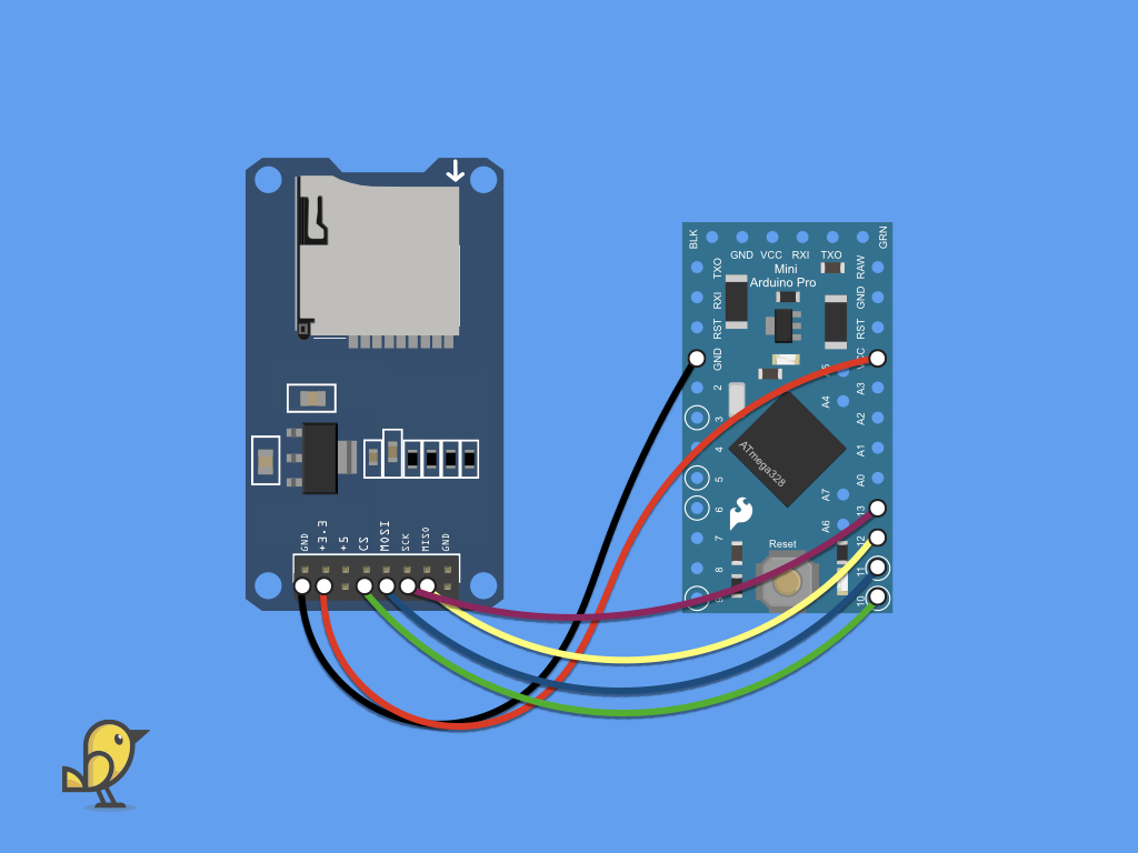
Attach a F-F jumper wire from SCK on the SD card module to digital pin 13 on the Pro Mini.
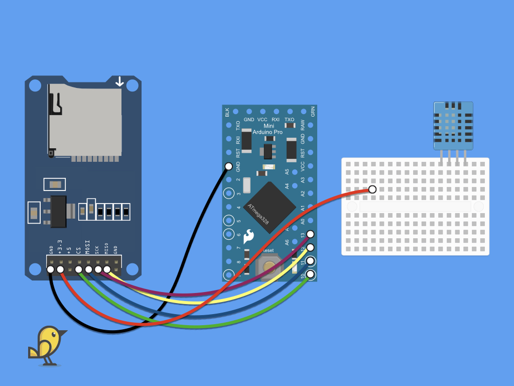
Next, insert the DHT11 temperature and humidity sensor into the mini breadboard.
Then, remove the F-F red jumper wire from VCC on the Pro mini.
Plug this end of the jumper wire into the breadboard, instead.
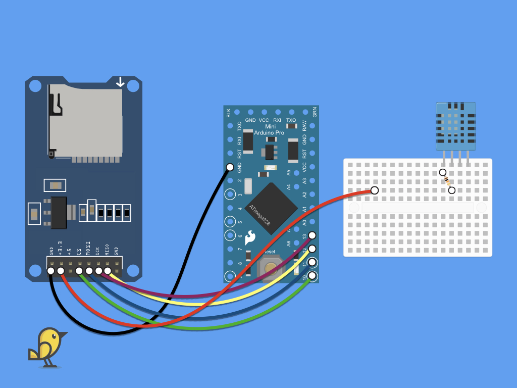
Insert the 10k ohm resistor into the breadboard, so that pins 1 and 2 of the DHT11 are bridged.

Now connect a red jumper wire from pin 1 of the DHT11 sensor to the same breadboard row as the other red jumper wire connected to the SD card module.
Insert another red jumper wire from the breadboard to the VCC pin on the Pro Mini.
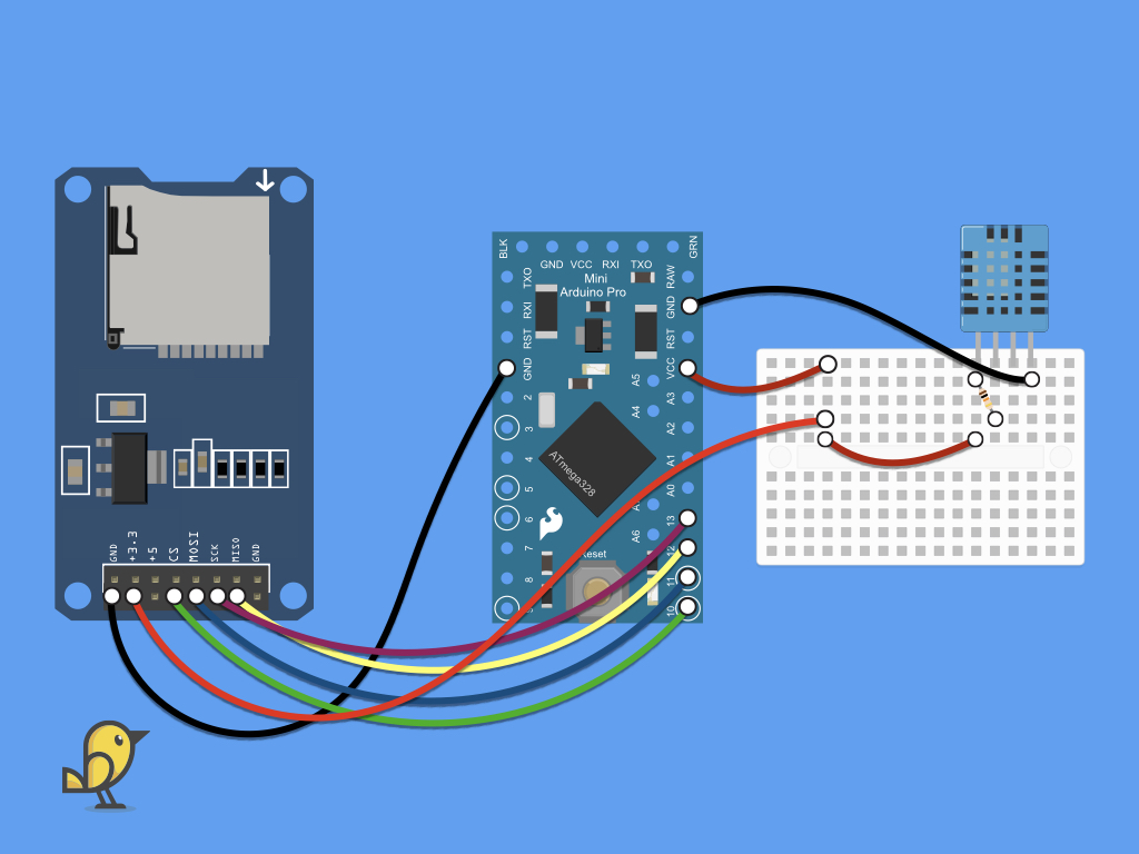
Attach a black jumper wire from the GND pin of DHT11 to GND on the Pro Mini.
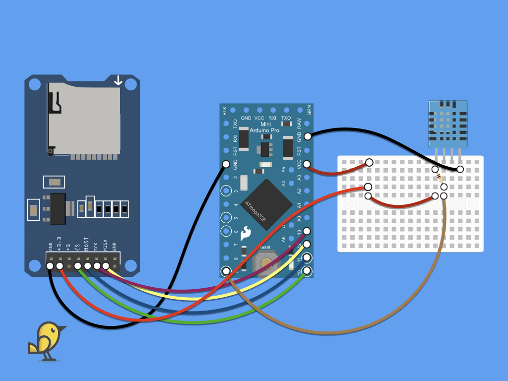
Finally, connect a jumper wire from the DATA pin on the DHT11 to digital pin 9 on the Pro Mini.
If you are using a Little Bird Uno R3 or other 5V Arduino board, you may need to use a logic level converter (such as a CMOS hex buffer IC, the 4050). Similar to many recent electronic devices, the SD card operates on a 3.3V logic level. However, Arduino boards such as the Little Bird Uno R3 outputs 5 volts on their digital logic output. A direct connection of 5V to the SD card could damage it.
#include <SPI.h>        // Include SPI library (needed for the SD card)
#include <SD.h>         // Include SD library
#include <DHT.h>        // Include DHT sensor library
First, the SD card module uses SPI, so you will need to import the SPI library with: #include <SPI.h>
Next, there is a built-in SD library which depends on three other internal libraries that can handle card and filesystem-specific functions. The library is easy to use, import it with: #include <SD.h>
Finally, include the DHT library.
#include <SPI.h>        // Include SPI library (needed for the SD card)
#include <SD.h>         // Include SD library
#include <DHT.h>        // Include DHT sensor library

#define DHTPIN 9            // DHT11 data pin is connected to Arduino pin 9
#define DHTTYPE DHT11       // DHT11 sensor is used
DHT dht(DHTPIN, DHTTYPE);   // Initialise DHT library
Define the DHT pin as 9, as the data pin is connected to digital pin 9.
Define the type of DHT sensor being used, in this case, it would be DHT11.
Then, initialise the DHT library with DHT dht(DHTPIN, DHTTYPE);
 #include <SPI.h>        // Include SPI library (needed for the SD card)
#include <SD.h>         // Include SD library
#include <DHT.h>        // Include DHT sensor library

#define DHTPIN 9            // DHT11 data pin is connected to Arduino pin 9
#define DHTTYPE DHT11       // DHT11 sensor is used
DHT dht(DHTPIN, DHTTYPE);   // Initialize DHT library

File dataFile;
Now create a File object, which can then be opened as well as have other file actions done to it.
#include <SPI.h>        // Include SPI library (needed for the SD card)
#include <SD.h>         // Include SD library
#include <DHT.h>        // Include DHT sensor library

#define DHTPIN 9            // DHT11 data pin is connected to Arduino pin 9
#define DHTTYPE DHT11       // DHT11 sensor is used
DHT dht(DHTPIN, DHTTYPE);   // Initialize DHT library

File dataFile;

void setup() {
  // Start serial communications
  Serial.begin(9600);
  while (!Serial)
    ; // wait for serial port to connect.
  Serial.print("Initialising SD card...");
  if (!SD.begin()) {
    Serial.println("initialisation failed!");
    while (1);
  }
  Serial.println("initialisation done.");
  delay(1000);
}
Next, in setup, use the Serial.begin command to start serial communication.
Then, add a while loop to setup so that it will wait for the serial port to connect. Once connected, it will print "Initialising SD card... " to the monitor.
Next, add an if statement in setup, to check if an SD card is detected and the library is initialised. If an SD card is detected, SD.begin returns true.
If SD.begin returns true, "initialisation done." will be printed to the serial monitor. Otherwise, "initialisation failed!" will be printed instead.
If SD.begin returns true, "initialisation done." will be printed to the serial monitor. Otherwise, "initialisation failed!" will be printed instead.
#include <SPI.h>        // Include SPI library (needed for the SD card)
#include <SD.h>         // Include SD library
#include <DHT.h>        // Include DHT sensor library

#define DHTPIN 9            // DHT11 data pin is connected to Arduino pin 9
#define DHTTYPE DHT11       // DHT11 sensor is used
DHT dht(DHTPIN, DHTTYPE);   // Initialize DHT library

File dataFile;

void setup() {
  // Start serial communications
  Serial.begin(9600);
  while (!Serial)
    ; // wait for serial port to connect.
  Serial.print("Initialising SD card...");
  if (!SD.begin()) {
    Serial.println("initialisation failed!");
    while (1);
  }
  Serial.println("initialisation done.");
  delay(1000);
}

uint16_t line = 1;

void loop()
{
  const unsigned long fiveMinutes = 5 * 60 * 1000UL;
  static unsigned long lastSampleTime = 0 - fiveMinutes;  // initialise such that a reading is due the first time through loop()

  unsigned long now = millis();
  if (now - lastSampleTime >= fiveMinutes)
  {
    lastSampleTime += fiveMinutes;
    // add code to take temperature reading here
    // Reading temperature or humidity takes about 250 milliseconds!
    // Sensor readings may also be up to 2 seconds 'old' (its a very slow sensor)
    // Read temperature in degree Celsius
    byte Temp = dht.readTemperature();

    dataFile = SD.open("DHT11Log.txt", FILE_WRITE);

    // if the file opened okay, write to it:
    if (dataFile) {
      Serial.print(line);
      Serial.print(":    Temperature = ");
      Serial.print(Temp);
      Serial.println("°C ");
      // Write data to SD card file (DHT11Log.txt)
      dataFile.print(line++);
      dataFile.print(":    Temperature = ");
      dataFile.print(Temp);
      dataFile.println("°C ");
      dataFile.close();

    }
    // if the file didn't open, print an error:
    else
      Serial.println("error opening DHT11Log.txt");
  }
  // add code to do other stuff here
}
Add the following code to get a temperature reading every 5 minutes, and record this temperature measurement into a text file on the SD card.
