
Beginner
Analog Inputs and micro:bit
Learn about analog inputs using a potentiometer and micro:bit
By Cherie Tan
What is the difference between a digital input and an analog input?
In this guide, you will be introduced to analog inputs using an external potentiometer. Learn to program it using MakeCode to measure its voltage.
Once you have finished this guide, you will understand what analog inputs are as well as how to use potentiometers with the micro:bit.
You're probably already familiar with using a potentiometer as they are commonly found on many electrical devices, such as in audio equipment where they are used for volume control. After all, potentiometers are sensors! What's a sensor? Simply put, a sensor is a device that receives and responds to a signal.
Potentiometers are analog input sensors. While digital sensors deal with values that are either â1â or â0â, analog sensor values are continuous. Analog sensors are able to tell us not just whether it senses something, but also how much of that something it senses.
Potentiometers are analog input sensors. While digital sensors deal with values that are either â1â or â0â, analog sensor values are continuous. Analog sensors are able to tell us not just whether it senses something, but also how much of that something it senses.
In the case of the potentiometer, it measures electric potential, also known as voltage.
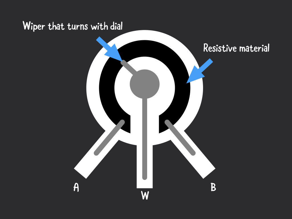
It has three pins.
Two terminals (labelled 'A' and 'B' in the diagram) are connected to a resistive material, while a third terminal is connected to an adjustable wiper (labelled 'W' in the diagram).
The resistance between the two outer terminals is fixed; it is the maximum resistance of the potentiometer.
The resistance between the middle terminal and either one of the outer terminals ranges from 0 Ω to the maximum resistance of the potentiometer as the knob is moved.
Step 1 — What is a potentiometer?
You're probably already familiar with using a potentiometer as they are commonly found on many electrical devices, such as in audio equipment where they are used for volume control. After all, potentiometers are sensors! What's a sensor? Simply put, a sensor is a device that receives and responds to a signal.
Potentiometers are analog input sensors. While digital sensors deal with values that are either â1â or â0â, analog sensor values are continuous. Analog sensors are able to tell us not just whether it senses something, but also how much of that something it senses.
Potentiometers are analog input sensors. While digital sensors deal with values that are either â1â or â0â, analog sensor values are continuous. Analog sensors are able to tell us not just whether it senses something, but also how much of that something it senses.
In the case of the potentiometer, it measures electric potential, also known as voltage.
It has three pins.
Two terminals (labelled 'A' and 'B' in the diagram) are connected to a resistive material, while a third terminal is connected to an adjustable wiper (labelled 'W' in the diagram).
The resistance between the two outer terminals is fixed; it is the maximum resistance of the potentiometer.
The resistance between the middle terminal and either one of the outer terminals ranges from 0 Ω to the maximum resistance of the potentiometer as the knob is moved.
Two terminals (labelled 'A' and 'B' in the diagram) are connected to a resistive material, while a third terminal is connected to an adjustable wiper (labelled 'W' in the diagram).
The resistance between the two outer terminals is fixed; it is the maximum resistance of the potentiometer.
The resistance between the middle terminal and either one of the outer terminals ranges from 0 Ω to the maximum resistance of the potentiometer as the knob is moved.
Step 2 — The potentiometer module
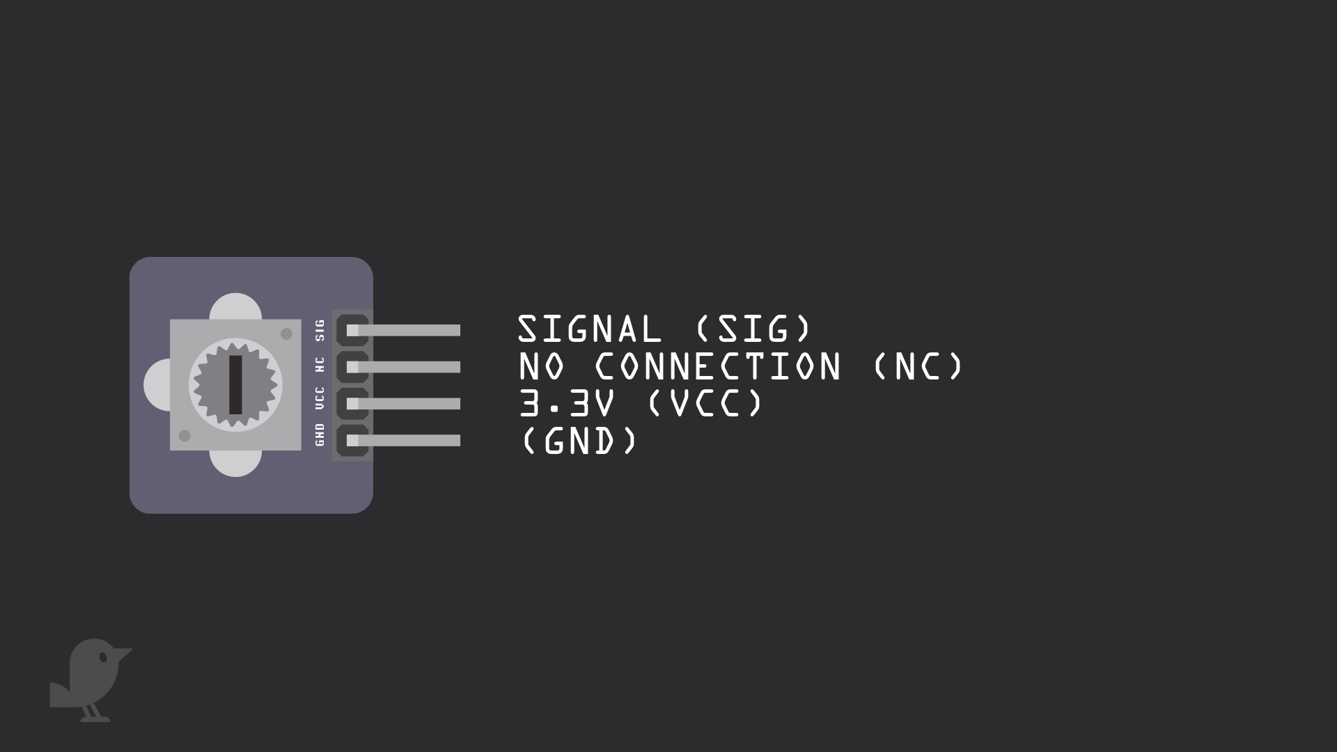
Let's take a closer look at the adjustable potentiometer module that will be used in this guide. There are four pins here:
SIG: Signal pin
NC: No Connection
3.3V : 'VCC' stands for Voltage Common Collector. We'll connect the VCC pin to 3.3V on the micro:bit
GND: In electronics, we define a point in a circuit to be a kind of zero volts or 0V reference point, on which to base all other voltage measurements. This point is called ground or GND.
Voltage is the difference in potential between two points. As it is difficult to talk about voltage without a reference point, we need another point to compare it to.
Step 3 — Connect module to breadboard
Step 4 — Connect GND to GND
Step 5 — Connect VCC to 3.3V
Step 6 — Connect P0 to SIG
Step 7 — Analog pins on micro:bit
In this guide, we have connected the potentiometer's signal pin to Pin 0 on the micro:bit
But you can also connect it to other pins:
Pin 0, 1 and 2 each are connected to a shared analog to digital converter or ADC for short. This means it can read a range of values apart from just '1' or '0'. This also means you can connect it to the potentiometer for analog signals.
Pin 3, 4 and 10 can also be used for analog signals.
For more information on the micro:bit and its features and pins, check out our guide, 'Meet the micro:bit'.
Step 8 — Get analogue value
basic.forever(function () {
    basic.showNumber(pins.analogReadPin(AnalogPin.P0))
    basic.pause(1000)
})
Copy and paste this code into the Javascript interface.
By using the 'analog read pin... ' block, the micro:bit takes the analogue voltage from the potentiometer and converts it to a digital value between 0 and 1023.
Step 9 — Get voltage value
let voltage = 0
let sensorVal = 0
let vcc = 0
vcc = 3.3
basic.forever(function () {
    sensorVal = pins.analogReadPin(AnalogPin.P0)
    voltage = sensorVal * (vcc / 1023)
    basic.showNumber(voltage)
    basic.pause(1000)
})
We can also convert this analogue value back to the voltage value.
Copy and paste this code into the Javascript interface, replacing the existing code.
Copy and paste this code into the Javascript interface, replacing the existing code.
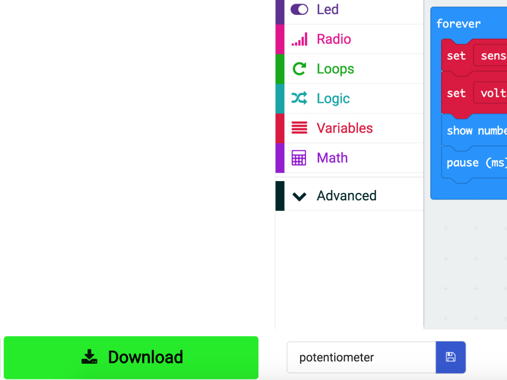
If you would like to use MakeCode blocks:
Create a new variable and name it 'vcc', give it a value of '3.3' as we have connected the 'VCC' pin on the module to '3.3V' on the micro:bit.
Then create another variable, 'sensorVal' and place an 'analog read pin P0' block in it.
The analog value from Pin 0 will be placed in this variable.
Finally, create a variable and name it 'voltage'. We'll then convert the sensor value to voltage.
Show the voltage value with a 'show number ...' block.
The equivalent code in MakeCode blocks can be found by clicking on the 'Blocks' button up the top in the MakeCode editor.
Step 10 — Upload the code to micro:bit
Click on the Download button on the bottom left-hand corner of MakeCode editor
Find the hex file
Open up Finder on the MacOS or Explorer on Windows, and drag the hex file into MICROBIT under 'Devices' on the macOS.
The micro:bit will flash for a few seconds while the code uploads
To upload the hex file to the micro:bit, first connect the micro:bit to your computer using a microUSB cable
Parts List
Required Parts (1)
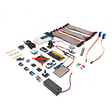
Project Summary
1 part total
Required parts
$79.35
Total (required)
$79.35
Unavailable items will be skipped
