Light Dependent Resistor
Sense light with your Arduino
Written By: Cherie Tan
Difficulty
Easy
Steps
7
Light-dependent resistors, also known as photo-resistors, are sensors that allow the detection of light. They are not only useful but are small and inexpensive.
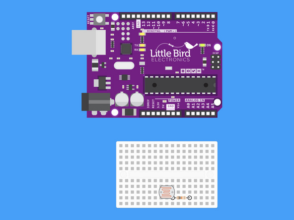
In this guide, you will learn to use a light-dependent resistor with the Arduino. We will use a Little Bird Uno R3 board, a mini breadboard, a 10k ohm resistor, some jumper wires, and a light-dependent resistor. You will learn to hook it up to the Arduino board, and measure the relative brightness of the environment.
Some examples of projects that require the use of light-dependent resistors include a noisemaker and a line-following robot.

Insert your LDR into your Breadboard.
The LDR is not polarised so the orientation of the LDR doesn't matter. Just be sure that the legs are not in the same row. (Note our breadboard is rotated 90º).
Insert your 10k Ohm resistor such that one of the resistor's legs shares a row with one of the legs of the LDR.
Your 10k Ohm resistor has the colour bands: "Brown, Black, Black, Red, Brown".

From the row where the legs share, use your white jumper wire and insert it into your Arduino's Analogue 0 Pin.
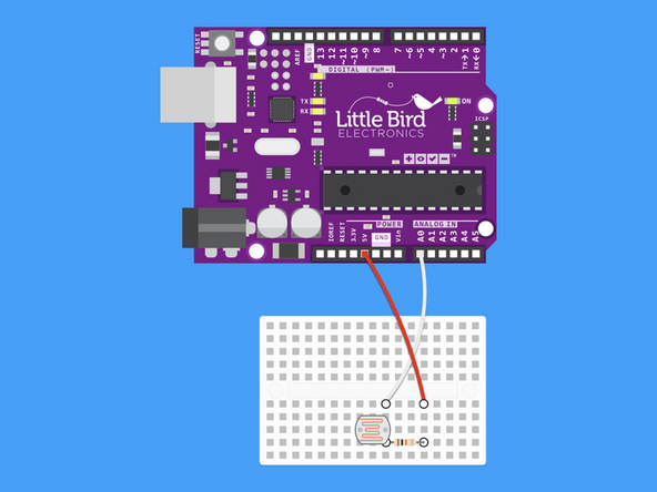
Run a red jumper wire from your Arduino's 5V pin to the other leg of your 10k resistor
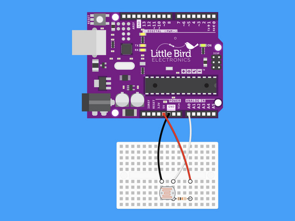
From the row with just the LDR leg put the black jumper wire and run it to GND (ground)
int ldr = 0;            //analogue pin to which LDR is connected
int ldr_value = 0; //variable to store LDR values

void setup()
{
   Serial.begin(9600); //start the serial monitor
}

void loop()
{
   ldr_value = analogRead(ldr);   //reads the LDR values
   Serial.println(ldr_value);          //prints the LDR values to the serial monitor
   delay(100);  //wait
}
Copy and Paste this code into your Arduino IDE.
Upload the code to your Arduino.
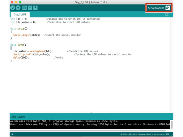
Now open the Serial Monitor. This is the button with the magnifying glass on the top right hand corner.
This will open a new window with values appearing.
When you cover the top of the LDR the values should go up > 500 . If you shine a torch on it the values will go down < 40.
Graphical representation is available using Serial Plotter (Tools → Serial Plotter menu).