Handheld Retrogaming Console
Build a handheld retro gaming console with the Raspberry Pi
Written By: Cherie Tan
Difficulty
Hard
Steps
16
Ever wanted to create your own handheld retro gaming device?
In this guide, we'll walk you through on how to create your own with the Raspberry Pi Zero W, a Teensy 2.0 microcontroller, soft tactile push buttons, a 3.7V 2500mAh LiPo battery, and a Powerboost 1000C.
Complete this guide to get started with creating your very own DIY portable gaming console.
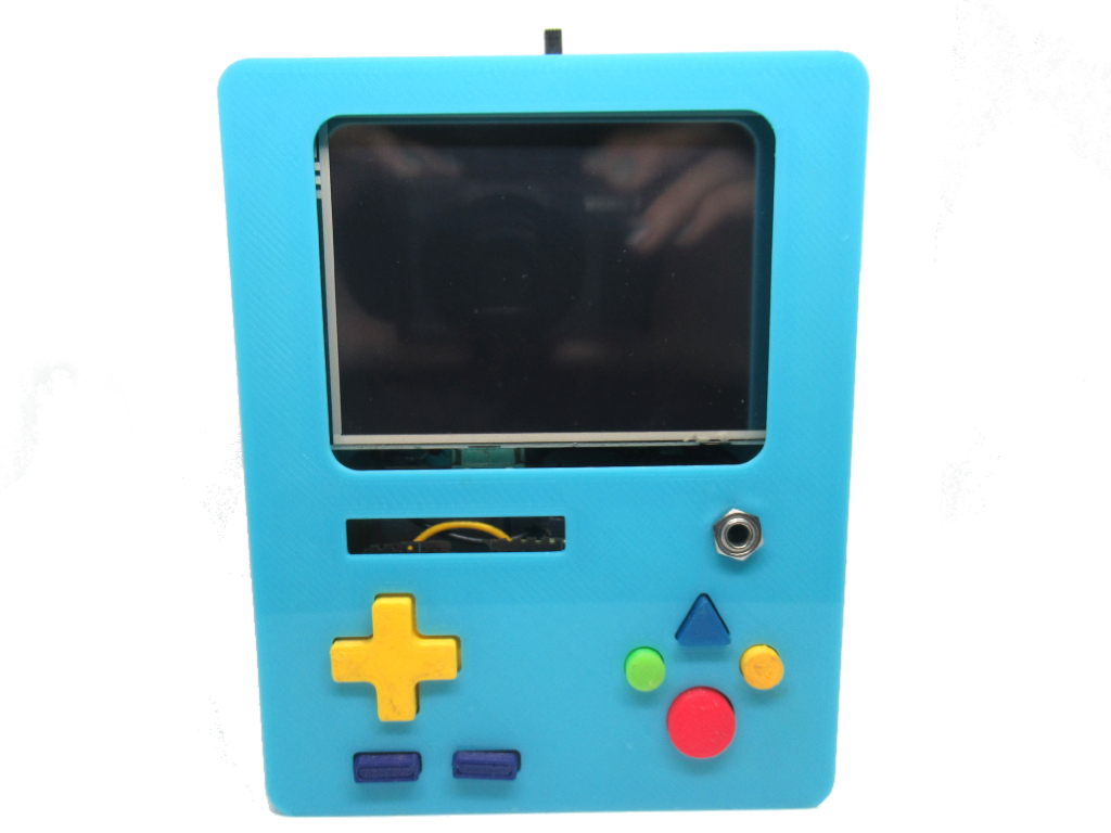
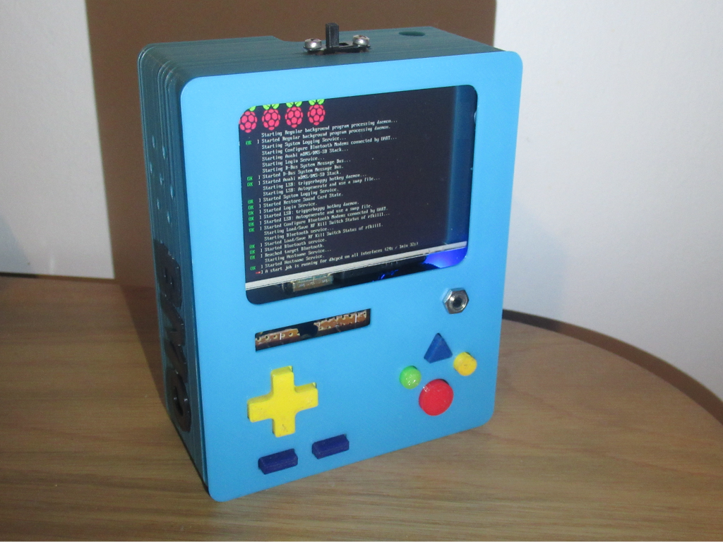
Build your own classic portable gaming device with the Raspberry Pi and a custom 3D-printed case of your own.
This build will have these features: Runs a wide range of emulators via Retropie such as GB, GBC, GBA, NES, SNES, SEGA etc.
10 X Soft-tactile buttons for a D-PAD, X, Y, A, B, Start, Select
2 X Standard pushbuttons for Right Trigger and Left Trigger
3.5'' TFT LCD screen
- Alternatively, you may want to use a larger LCD screen such as this 5'' LCD HDMI screen with Touch-screen capability
- For an even larger screen, we recommend this 7'' LCD HDMI screen with Touch-screen capability, too!
- If you do use a larger sized screen, you will need a different 3D printed case.
Runs on a 2500mAh LiPo battery
Power On/Off switch
Wi-Fi capability for easy ROM-transfer
While other models of the Raspberry Pi can be used to build a classic gaming device, in this guide we'll use a Raspberry Pi Zero W as its powerful enough to run many supported systems, as well as compact enough to fit in the 3D printed case.

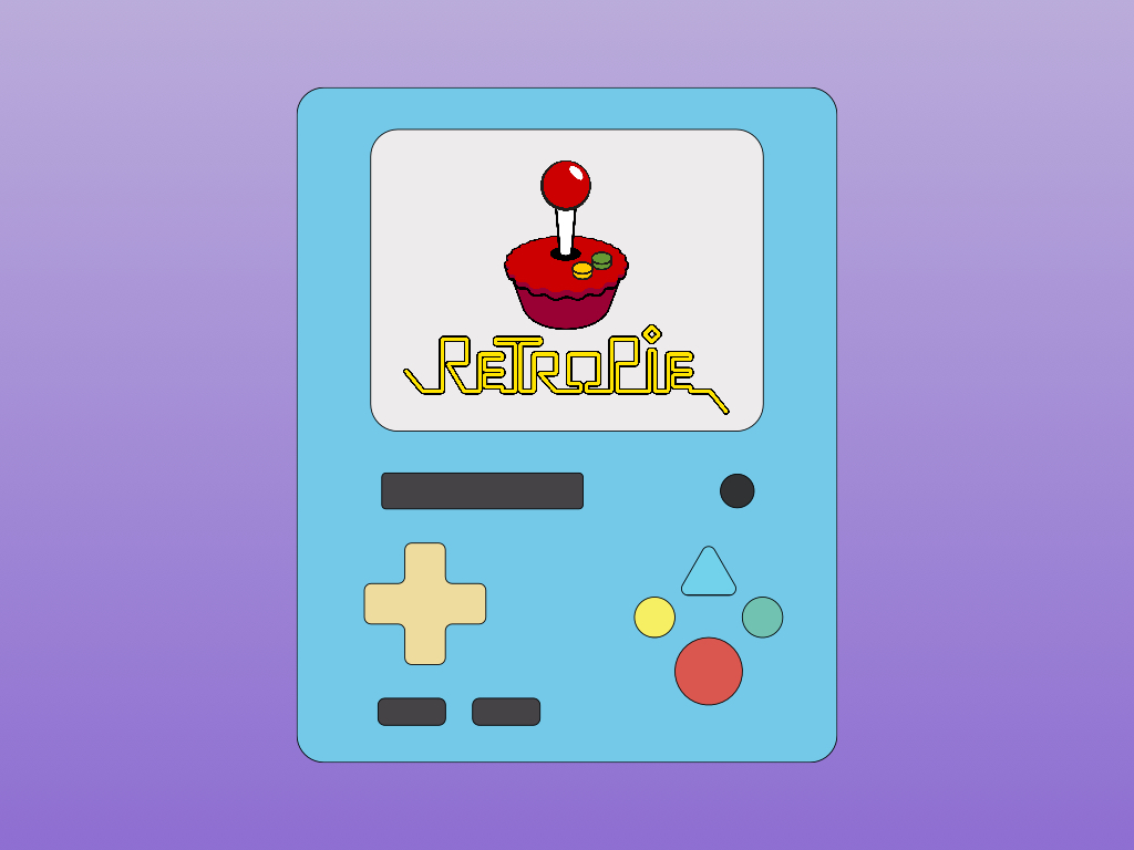
Retropie is an application for retro gaming on the Raspberry Pi and other boards such as the Odroid as well as on PC.
To install Retropie for the Raspberry Pi, you will need to download a pre-made image of Retropie. Go to the Downloads page on the official Retropie site: https://retropie.org.uk/download/
Download the appropriate pre-made image:
- Click on the button 'Raspberry Pi 0/1' if you are using a Raspberry Pi Zero W
- Click on the button 'Raspberry Pi 2/3' if you are using a Raspberry Pi 3B+
Flash the image onto the microSD card using a software such as Etcher
For more information on using Retropie, follow our previous guide on how to set up Retropie with the Raspberry Pi.
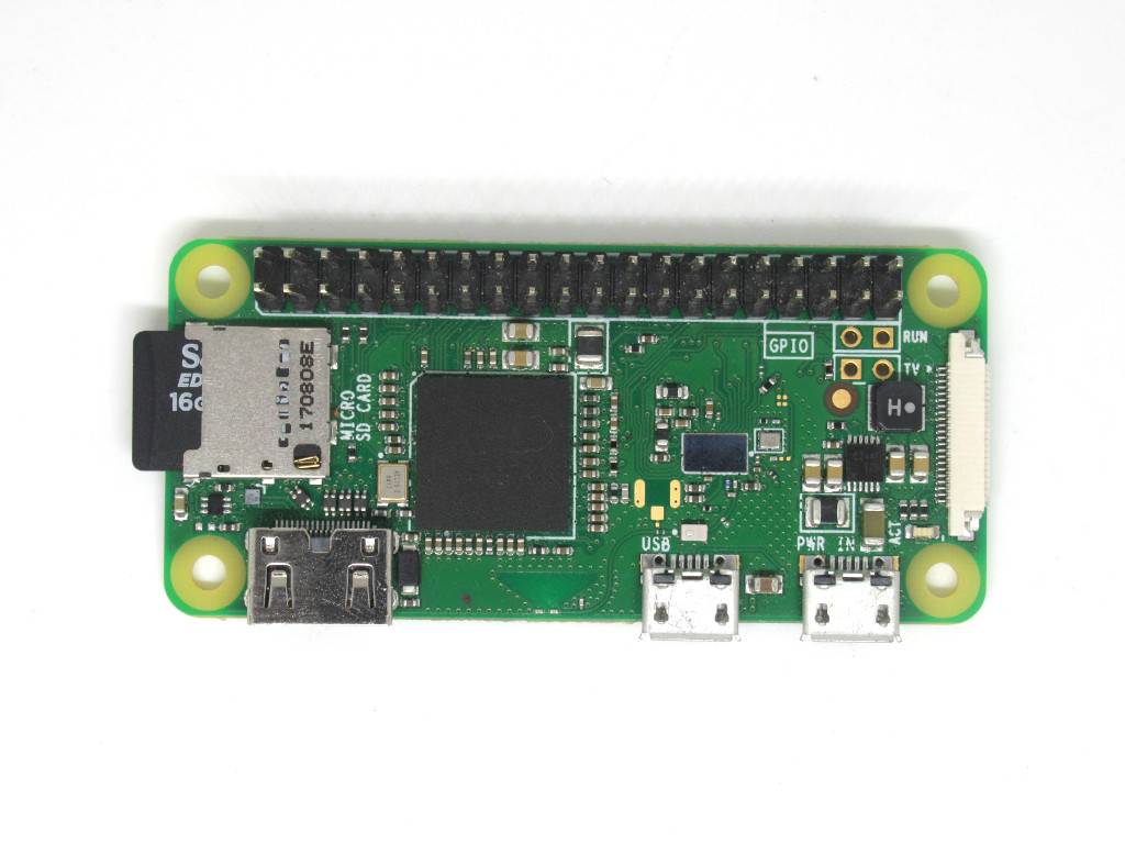
With Retropie on the microSD card, now insert it into the microSD slot on the Raspberry Pi.

The 3.5'' TFT screen comes fully assembled and ready to be plugged into your Raspberry Pi. Follow this guide on how to set up the Adafruit PiTFT 3.5'' Touch Screen.
Alternatively, if you are using the 5'' TFT LCD screen, follow our guide on how to set up the 5'' TFT LCD screen.
If you are using the 7'' screen, follow our guide on how to set up the 7'' TFT LCD screen.
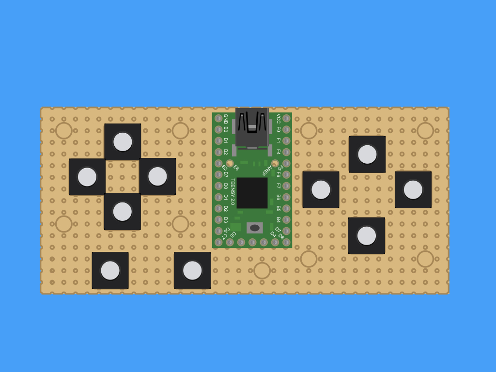
First, let's plan out the perf board assembly. The soft tactile pushbuttons and Teensy 2.0 will be connected to the perfboard as shown.
Solder the pushbuttons and teensy into place.
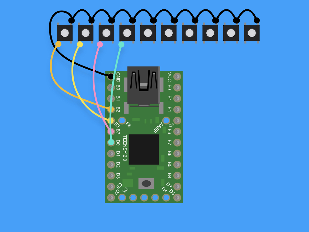
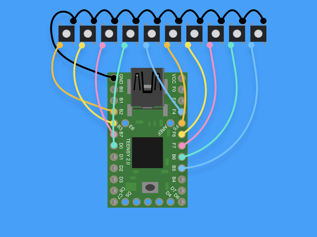
Wire up the Teensy 2.0 to the soft-tactile buttons:
- F4 = Up
- F5 = Down
- F6 = Left
- F7 = Right
- B6 = Start
- B5 = Select
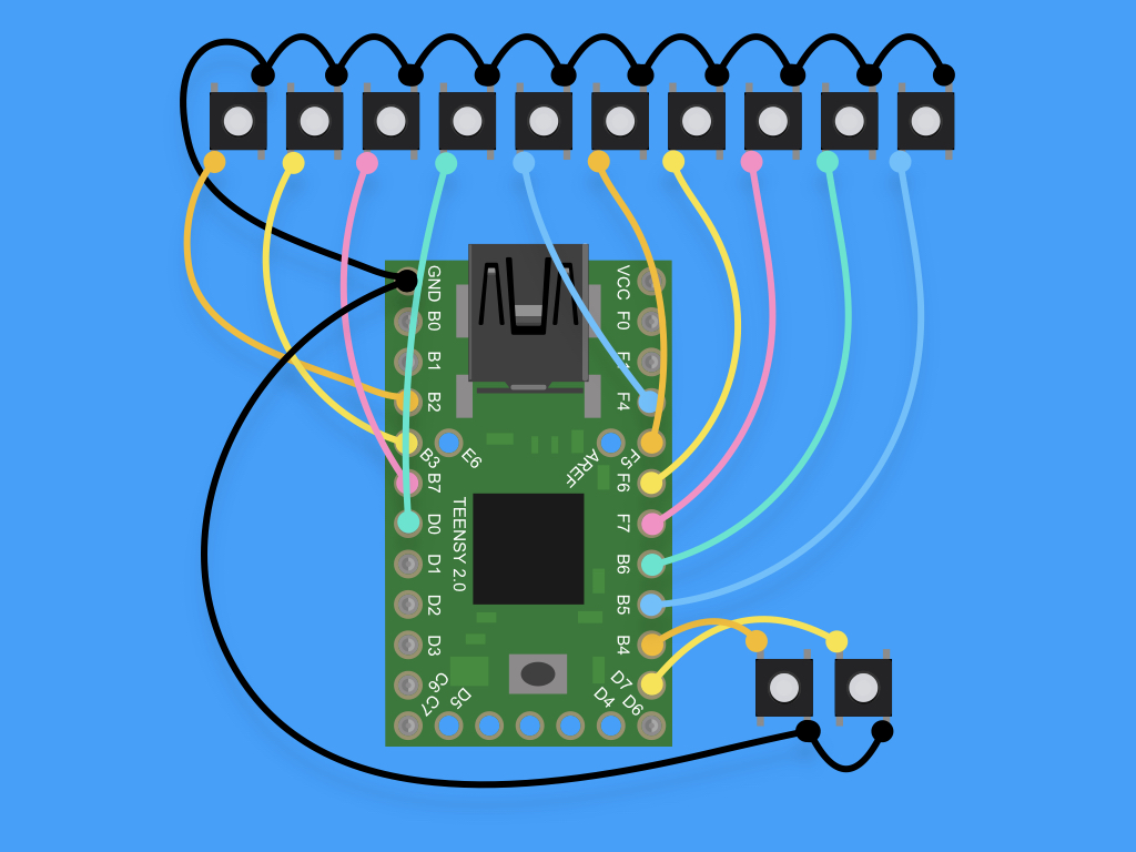
- B4 = Left Trigger
- B7 = Right Trigger
- B2 = A
- B3 = B
- B7 = X
- D0 = Y
Trim the remaining two leads.
Tin the leads by applying solder to them.
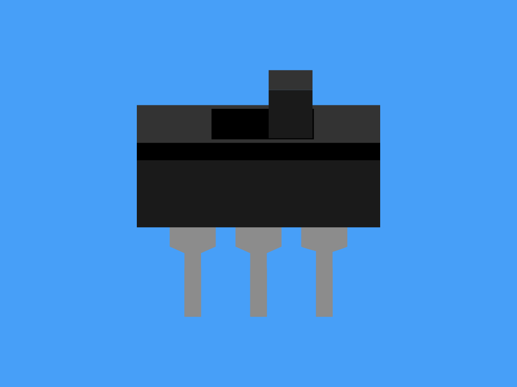
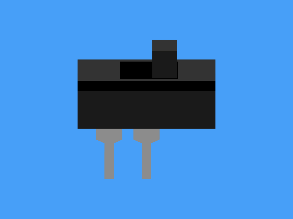
It's time to prepare the slide switch. This will be the power ON/OFF switch. First, cut off the lead on the far left or far right (but not the middle).
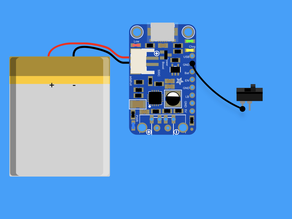
Solder a black wire from 'GND' on the Powerboost 1000C to the other lead on SPST switch
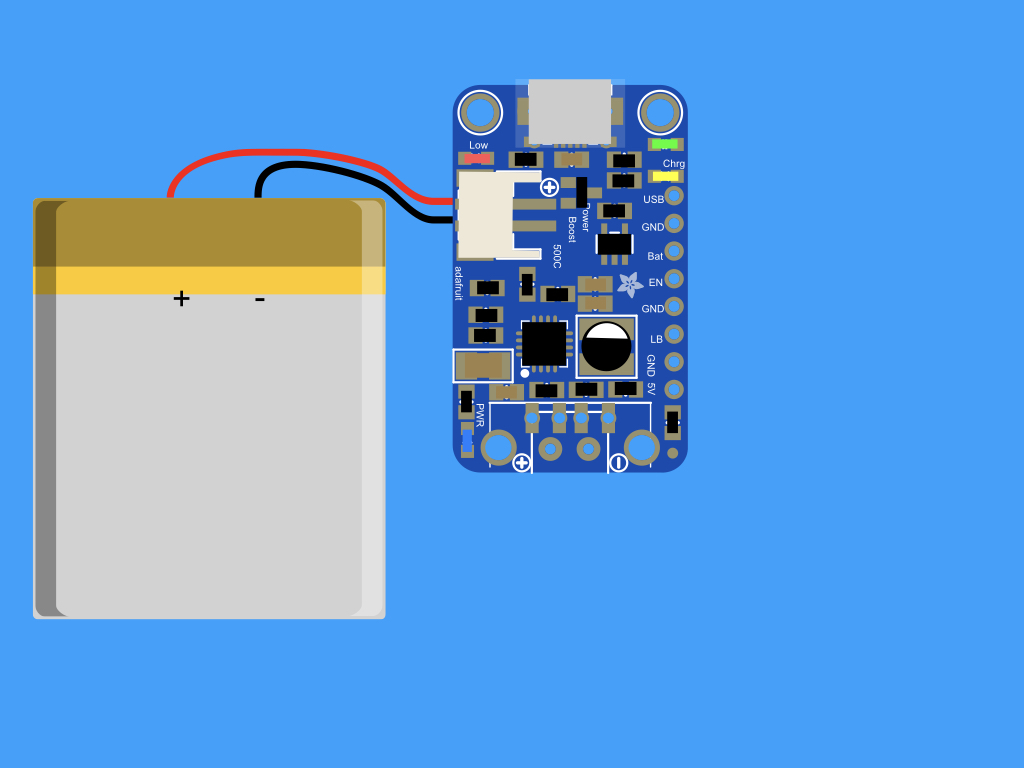
Connect the JST cable on the LiPo to the JST connector on the Powerboost 1000C
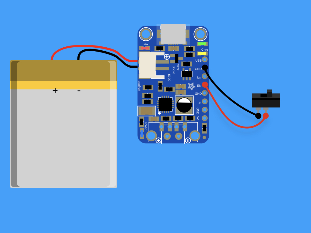
Solder a red wire from 'EN' on the Powerboost 1000C to the middle lead on SPST switch
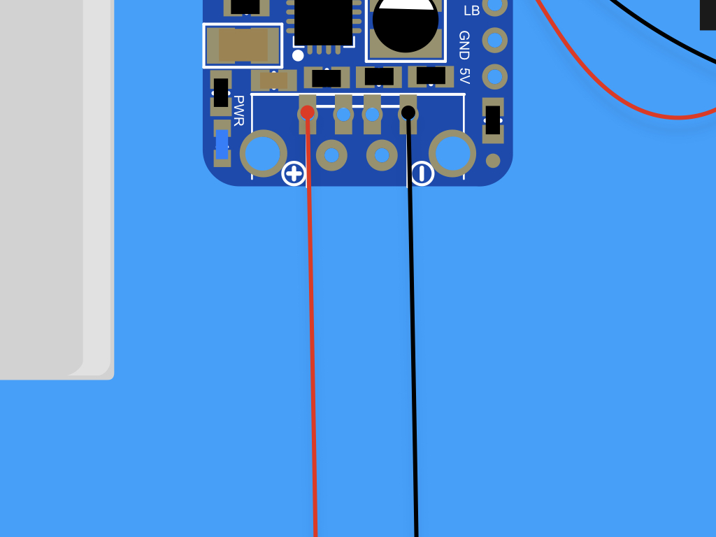
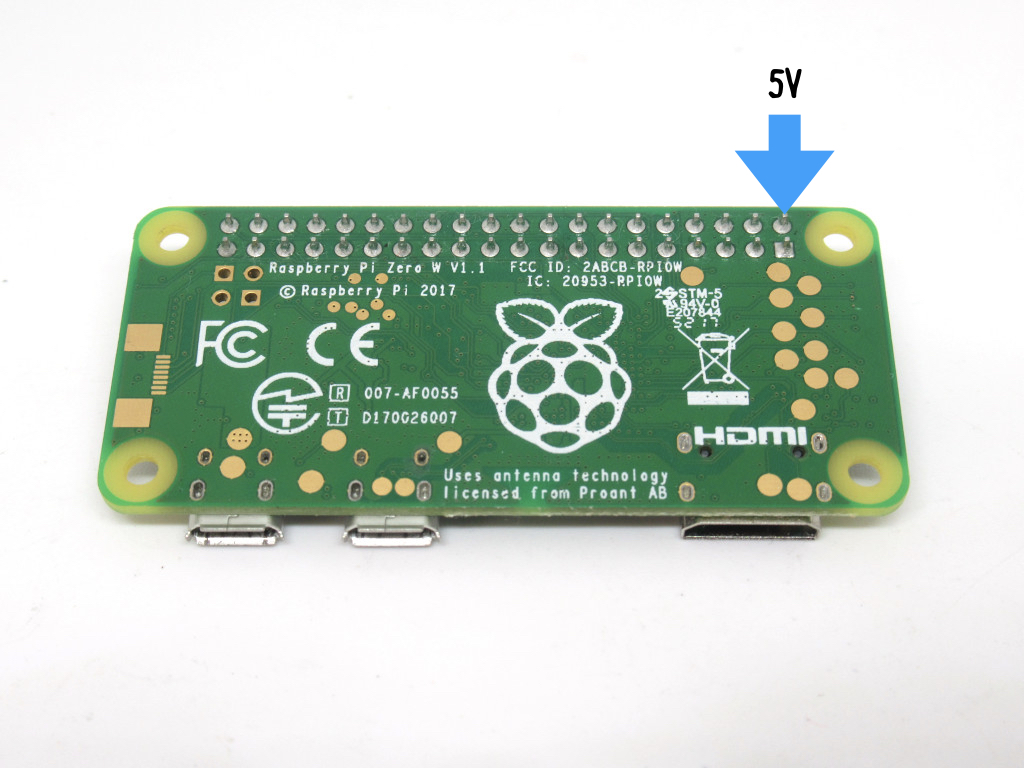
Finally, connect the Powerboost 1000C to the Raspberry Pi Zero W. First, solder a red wire from '+' on the Powerboost 1000C to '5V' on the Raspberry Pi Zero W
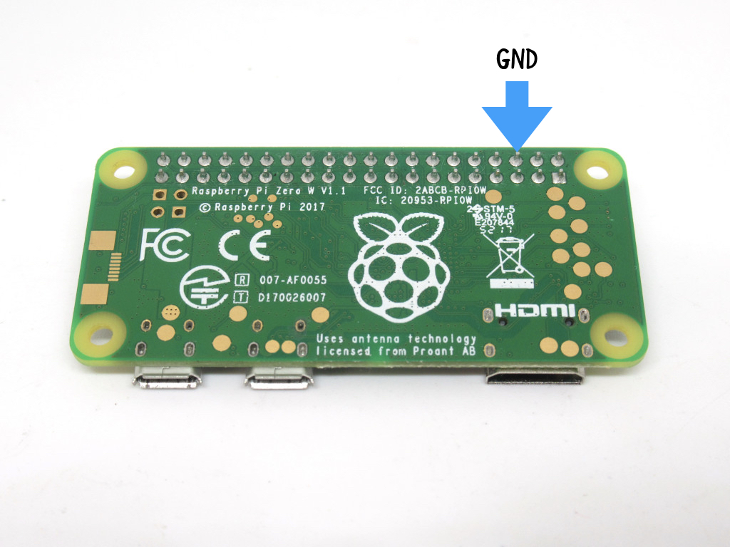
Solder a black wire from '-' on Powerboost 1000C to 'GND' on Raspberry Pi Zero W
To connect the Teensy to the Raspberry Pi Zero W, we'll use a USB to mini USB 5-pin cable.
- Ideally, use a right-angled cable for a better fit with the 3D printed case.
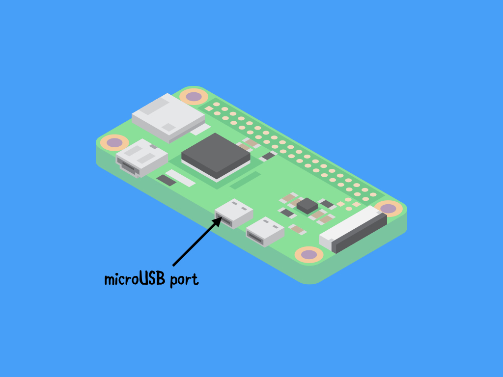
Attach the microUSB to USB adapter to the Raspberry Pi Zero W.
- Please make sure it is attached to the microUSB port labelled 'USB'
- The other microUSB port should only be attached to a power supply
Connect one end of the cable to the adapter.
Connect the other end of the cable to the mini USB port on the Teensy.
In this guide, we'll use the RaspBMO case made by 3Derp on Thingiverse.
- Download the .STL files for the 3D printed case here.
- We recommend printing the case in PLA or ABS
- Print the buttons in NinjaFlex or other flexible material
- Assemble the case and components together with pan-head screws.
- Note: More information on assembling the case can be found on Thingiverse.
If you are using a larger sized screen, you may want to pick a different 3D printed case. There are many available on Thingiverse!
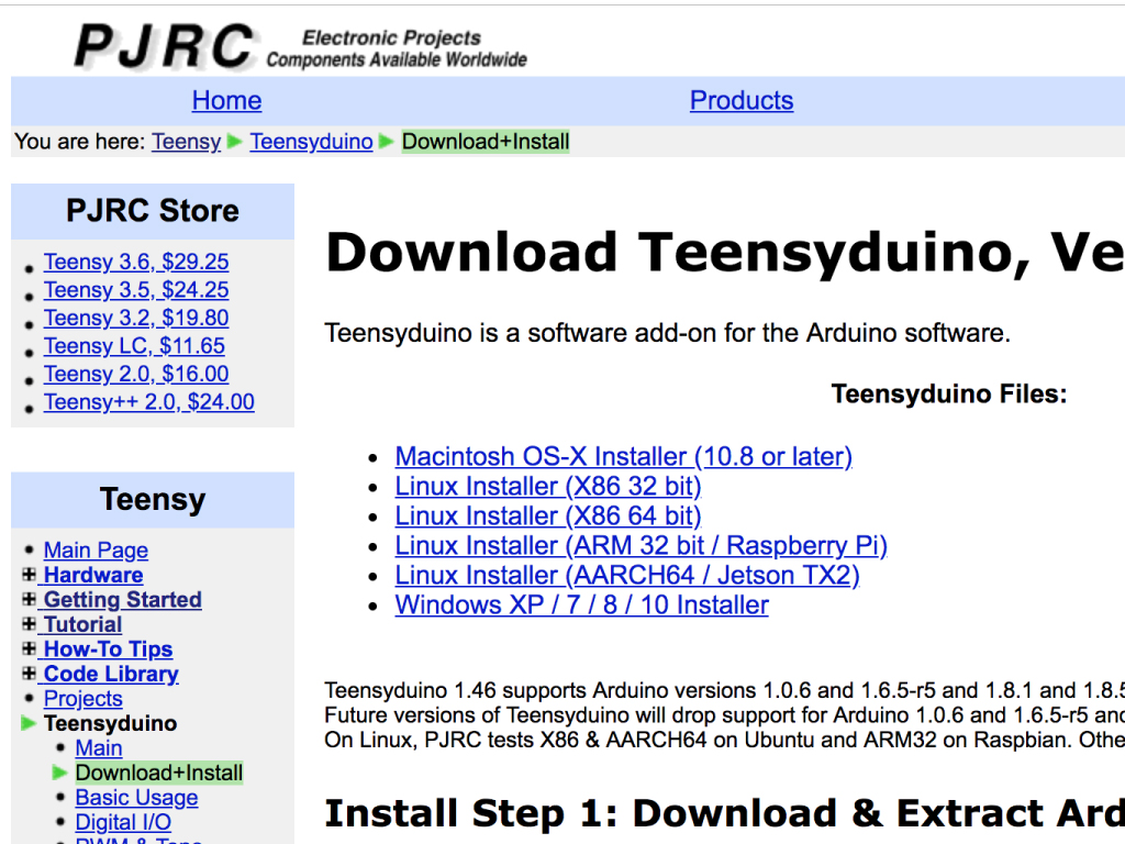
As the Arduino IDE does not come with support for the Teensy, you will need to run the Teensyduino installer.
Choose the installer for your operating system.
During installation, it will ask you to specify the location of your Arduino software.
The "Next" button will only activate until a directory containing the Arduino software is selected.
#include <Bounce.h>

// Create Bounce objects for each button.  The Bounce object
// automatically deals with contact chatter or "bounce", and
// it makes detecting changes very simple.
Bounce button0 = Bounce(2, 10);
Bounce button1 = Bounce(3, 10);  // 10 = 10 ms debounce time
Bounce button2 = Bounce(4, 10);  // which is appropriate for
Bounce button3 = Bounce(5, 10);  // most mechanical pushbuttons
Bounce button4 = Bounce(14, 10);
Bounce button5 = Bounce(15, 10);
Bounce button6 = Bounce(16, 10);
Bounce button7 = Bounce(17, 10);
Bounce button8 = Bounce(18, 10);
Bounce button9 = Bounce(19, 10);
Bounce button10 = Bounce(12, 10);
Bounce button11 = Bounce(13, 10);


void setup() {
  // Configure the pins for input mode with pullup resistors.
  // The pushbuttons connect from each pin to ground.  When
  // the button is pressed, the pin reads LOW because the button
  // shorts it to ground.  When released, the pin reads HIGH
  // because the pullup resistor connects to +5 volts inside
  // the chip.  LOW for "on", and HIGH for "off" may seem
  // backwards, but using the on-chip pullup resistors is very
  // convenient.  The scheme is called "active low", and it's
  // very commonly used in electronics... so much that the chip
  // has built-in pullup resistors!
  pinMode(2, INPUT_PULLUP);
  pinMode(3, INPUT_PULLUP);
  pinMode(4, INPUT_PULLUP);
  pinMode(5, INPUT_PULLUP);
  pinMode(14, INPUT_PULLUP);
  pinMode(15, INPUT_PULLUP);
  pinMode(16, INPUT_PULLUP);  // Teensy++ LED, may need 1k resistor pullup
  pinMode(17, INPUT_PULLUP);
  pinMode(18, INPUT_PULLUP);
  pinMode(19, INPUT_PULLUP);
  pinMode(12, INPUT_PULLUP);
  pinMode(13, INPUT_PULLUP);

}

void loop() {
  // Update all the buttons.  There should not be any long
  // delays in loop(), so this runs repetitively at a rate
  // faster than the buttons could be pressed and released.
  button0.update();
  button1.update();
  button2.update();
  button3.update();
  button4.update();
  button5.update();
  button6.update();
  button7.update();
  button8.update();
  button9.update();
  button10.update();
  button11.update();

  // Check each button for "falling" edge.
  // Update the Joystick buttons only upon changes.
  // falling = high (not pressed - voltage from pullup resistor)
  //           to low (pressed - button connects pin to ground)
  if (button0.fallingEdge()) {
    Joystick.button(1, 1);
  }
  if (button1.fallingEdge()) {
    Joystick.button(2, 1);
  }
  if (button2.fallingEdge()) {
    Joystick.button(3, 1);
  }
  if (button3.fallingEdge()) {
    Joystick.button(4, 1);
  }
  if (button4.fallingEdge()) {
    Joystick.button(5, 1);
  }
  if (button5.fallingEdge()) {
    Joystick.button(6, 1);
  }
  if (button6.fallingEdge()) {
    Joystick.button(7, 1);
  }
  if (button7.fallingEdge()) {
    Joystick.button(8, 1);
  }
  if (button8.fallingEdge()) {
    Joystick.button(9, 1);
  }
  if (button9.fallingEdge()) {
    Joystick.button(10, 1);
  }
  if (button10.fallingEdge()) {
    Joystick.button(11, 1);
  }
  if (button11.fallingEdge()) {
    Joystick.button(12, 1);
  }

  // Check each button for "rising" edge
  // Update the Joystick buttons only upon changes.
  // rising = low (pressed - button connects pin to ground)
  //          to high (not pressed - voltage from pullup resistor)
  if (button0.risingEdge()) {
    Joystick.button(1, 0);
  }
  if (button1.risingEdge()) {
    Joystick.button(2, 0);
  }
  if (button2.risingEdge()) {
    Joystick.button(3, 0);
  }
  if (button3.risingEdge()) {
    Joystick.button(4, 0);
  }
  if (button4.risingEdge()) {
    Joystick.button(5, 0);
  }
  if (button5.risingEdge()) {
    Joystick.button(6, 0);
  }
  if (button6.risingEdge()) {
    Joystick.button(7, 0);
  }
  if (button7.risingEdge()) {
    Joystick.button(8, 0);
  }
  if (button8.risingEdge()) {
    Joystick.button(9, 0);
  }
  if (button9.risingEdge()) {
    Joystick.button(10, 0);
  }
  if (button10.risingEdge()) {
    Joystick.button(11, 0);
  }
  if (button11.risingEdge()) {
    Joystick.button(12, 0);
  }
}
Once the Teensyduino software has been installed, open up the Arduino IDE: Select Tools > Board> Teensy 2.0
Select 'Joystick' from Tools > USB Type
Copy and paste the following code into the Arduino IDE.
Verify and upload the code to the Teensy 2.0
There are multiple ways to transfer ROMs to the Raspberry Pi. Once you have assembled the components into the 3D printed case, it will be easier and much more convenient to transfer ROMs via SFTP. To transfer via SFTP, you will need a software such as Filezilla.
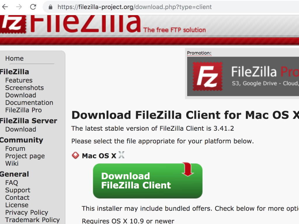
Download FileZilla here: https://filezilla-project.org/download.php?type=client
Click the 'Download' button
Run the installer and follow the installation instruction
Once complete, start Filezilla
Enter the password of your Raspberry Pi in the 'Password' field
- By default, this is 'raspberry'
Click the 'Connect' button
Then click 'OK'
To transfer ROMs, drop the files in the ~/RetroPie/roms/$CONSOLE folder, where $CONSOLE is the name of the target console, e.g. 'GBA' or 'SNES' etc.
Note: For this step, make sure you have SSH enabled on the Raspberry Pi.
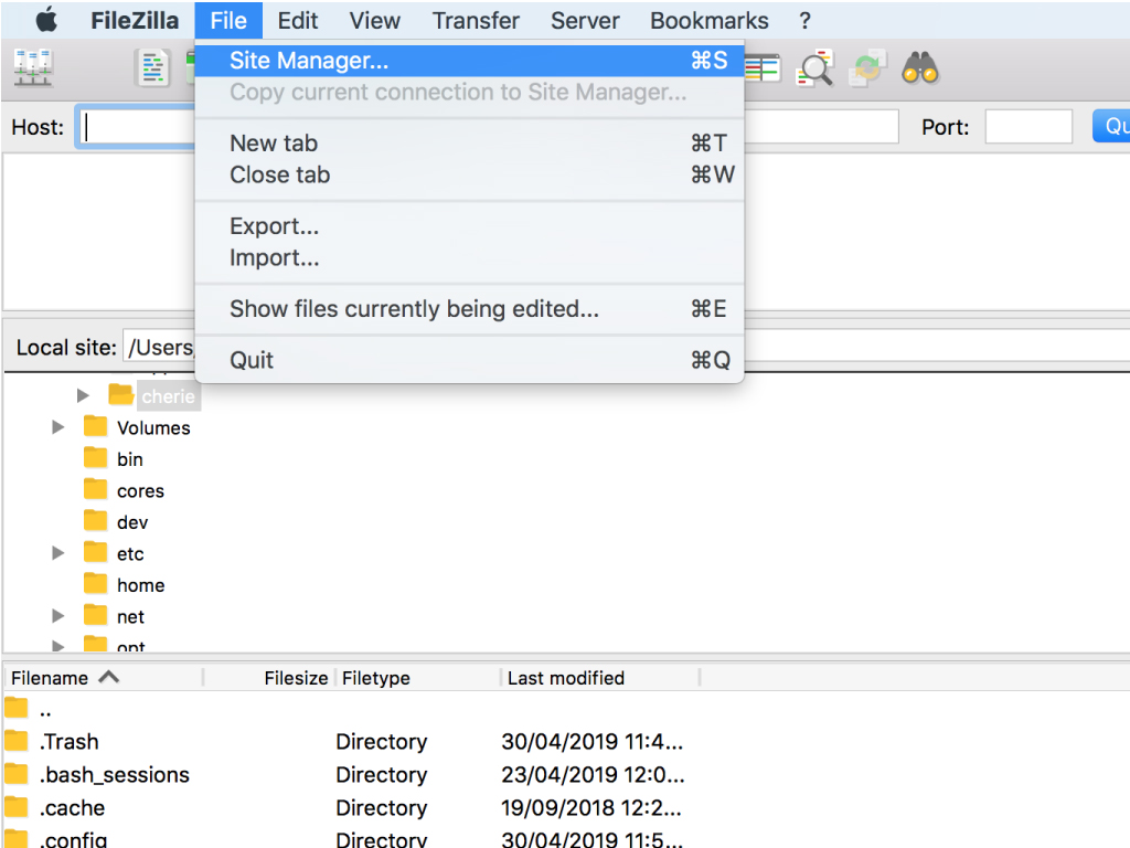
Click on File > Site Manager ...
Click on 'New Site' button
Name it as you like, in this guide we've named it 'Retropie handheld'
Change 'Protocol' to 'SFTP - SSH File Transfer Protocol'
The 'Host' should be set to the IP address of your Raspberry Pi
- To find the IP address, go into RetroPie options from the main menu, and select 'Show IP'
Enter the username of your Raspberry Pi in the 'User' field.
- By default, this is 'pi'
Some ideas on what to do next includes adding audio output to your build
This can be done on the Raspberry Pi Zero W with a USB Audio Adapter
Then connect it to this Panel Mount Stereo Audio Extension Cable - 1/8 / 3.5mm which will fit the 3D printed case
Note: As the Raspberry Pi Zero W only has one microUSB port, you may also need a USB hub.
This is just one of many ways to create a handheld retro gaming console. You may want to customise your build with more add-ons. Here are some ideas:
- Substitute the Raspberry Pi Zero W with a different model
- Add analog dual-axis joystick controls.